Flywheel unit of prime motor

A technology of flywheel device and prime mover, which is applied in the directions of flywheel, mechanical equipment, vibration suppression adjustment, etc., can solve the problem of increasing size, and achieve the effect of simple structure and compact axial size

Inactive Publication Date: 2005-11-09
HONDA MOTOR CO LTD
View PDF1 Cites 0 Cited by
  • Summary
  • Abstract
  • Description
  • Claims
  • Application Information

AI Technical Summary

Problems solved by technology

[0004] According to the conventional flywheel device, since the bearing is embedded in the flywheel body, it is necessary to ensure the required thickness for the insertion in the center of the flywheel body, and at the same time, a plate of the torsional vibration damper is fixed on the clutch side. Protruding protrusions, so there is a problem that the overall size of the device becomes larger in the axial direction

Method used


Image

  • Flywheel unit of prime motor
  • Flywheel unit of prime motor
  • Flywheel unit of prime motor

Examples


Embodiment Construction

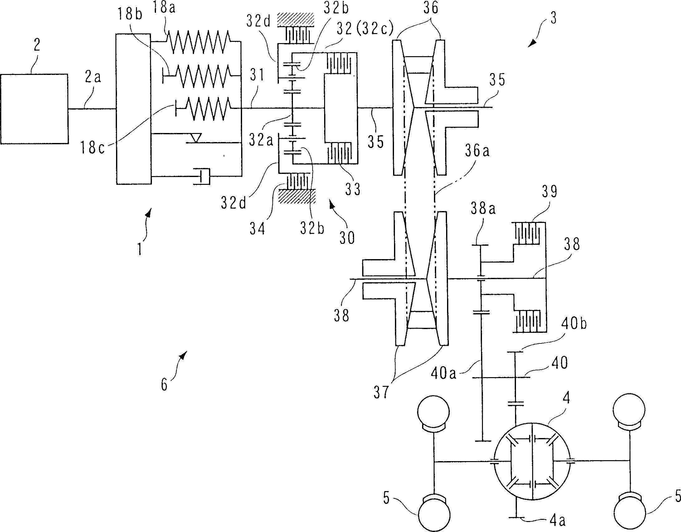
[0022] Next, a flywheel device 1 for a prime mover according to an embodiment of the present invention will be described with reference to the drawings. figure 1 A schematic configuration of a vehicle drive train using the flywheel device of this embodiment is shown. Such as figure 1 As shown, in the vehicle drive system 6, the engine 2 as the prime mover is connected to the driving wheels 5, 5 through the flywheel device 1, the automatic transmission 3, the differential gear mechanism 4, etc., so that the torque of the engine 2 is transmitted to On driving wheel 5,5.

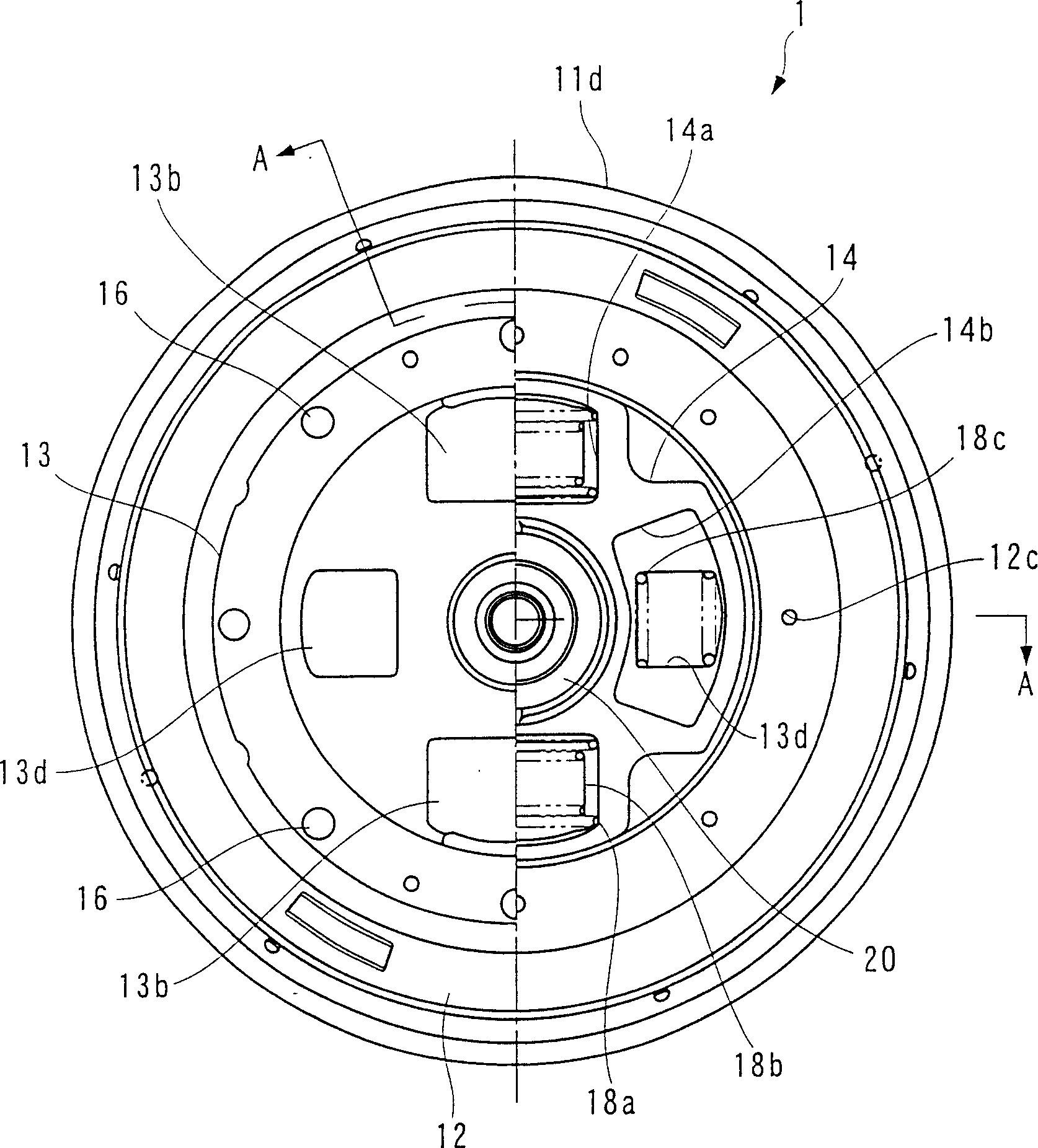
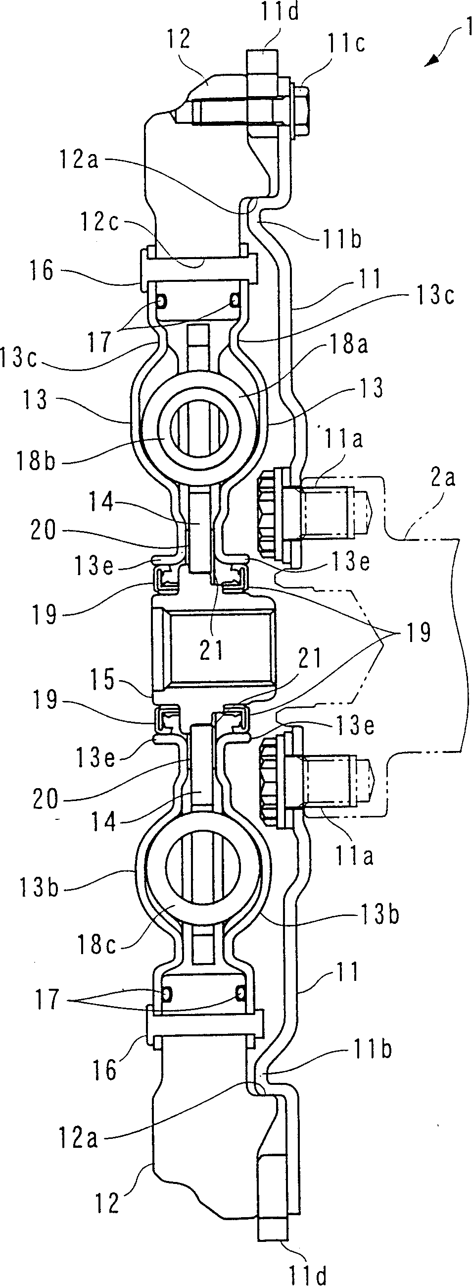
[0023] The flywheel device 1 is provided between the engine 2 and the automatic transmission 3 , and transmits the torque of the engine 2 to the automatic transmission 3 while reducing torque fluctuations of the engine 2 and attenuating torsional vibration. Such as figure 2 as well as image 3 As shown, the flywheel device 1 is composed of a driving plate 11, a mass ring 12, a pair of spring support plates...


PUM


Abstract

There is provided a flywheel device for a prime mover, which can be made compact in the axial size thereof and have an effectively increased inertial mass. The flywheel device is comprised of a drive plate and a mass ring. The drive plate has an annular projection and is attached to a crankshaft in a manner concentric with the crankshaft. The mass ring has an annular recess and is concentrically attached to the drive plate by the annular recess being fitted on the annular projection of the drive plate. The flywheel device transmits torque from an engine as the prime mover to the input shaft of an automatic transmission while reducing variation in the torque.

Description

technical field [0001] The present invention relates to a flywheel device for a prime mover that transmits prime mover torque while reducing prime mover torque variation and attenuating torsional vibration, such as a flywheel with a torsional vibration damper used in a vehicle drive system. Background technique [0002] A conventional flywheel device of this type is known, for example, as described in Japanese Utility Model Publication No. 57-12273. The flywheel device is integrally assembled with a flywheel main body and a torsional vibration damper (hereinafter referred to as "torsional vibration damper"), and is disposed between the engine and the clutch. The flywheel main body has a disk-shaped base and a protrusion protruding from the outer peripheral end of the base toward the clutch side. A crankshaft of the engine is attached to the center of the root, and a bearing for rotatably supporting the clutch input shaft is fitted in the center of the clutch-side surface of...

Claims


Application Information

Patent Timeline
Patent Type & Authority Patents(China)
IPC IPC(8): F16F15/123F16F15/131
CPCF16F15/1315Y10T74/2125
Inventor 渡边直人一条秀治角诚五月女浩
Owner HONDA MOTOR CO LTD
Why Eureka
Try Eureka