
Jet regulator

A jet flow regulator and jet flow regulation technology, which is applied to indoor sanitary pipe installations, water supply installations, buildings, etc., can solve the problems of restricting the possibility of use, restricting the possibility of structural design of the jet flow regulator, etc., and achieves strong braking of water flow speed. , Simple structure, low cost effect

Inactive Publication Date: 2005-12-07
NEOPERL
View PDF3 Cites 2 Cited by
  • Summary
  • Abstract
  • Description
  • Claims
  • Application Information

AI Technical Summary

Problems solved by technology

[0006] The construction of the insert part used in the known jet regulator according to DE-U-297 18 728, with the sleeve-shaped part forming a cylindrical segment and having pin segments, limits the structural design of the known jet regulator Possibilities and thus limited possibilities of use, and expensive die-casting tools are required for this

Method used


Image

  • Jet regulator
  • Jet regulator
  • Jet regulator

Examples


Embodiment Construction

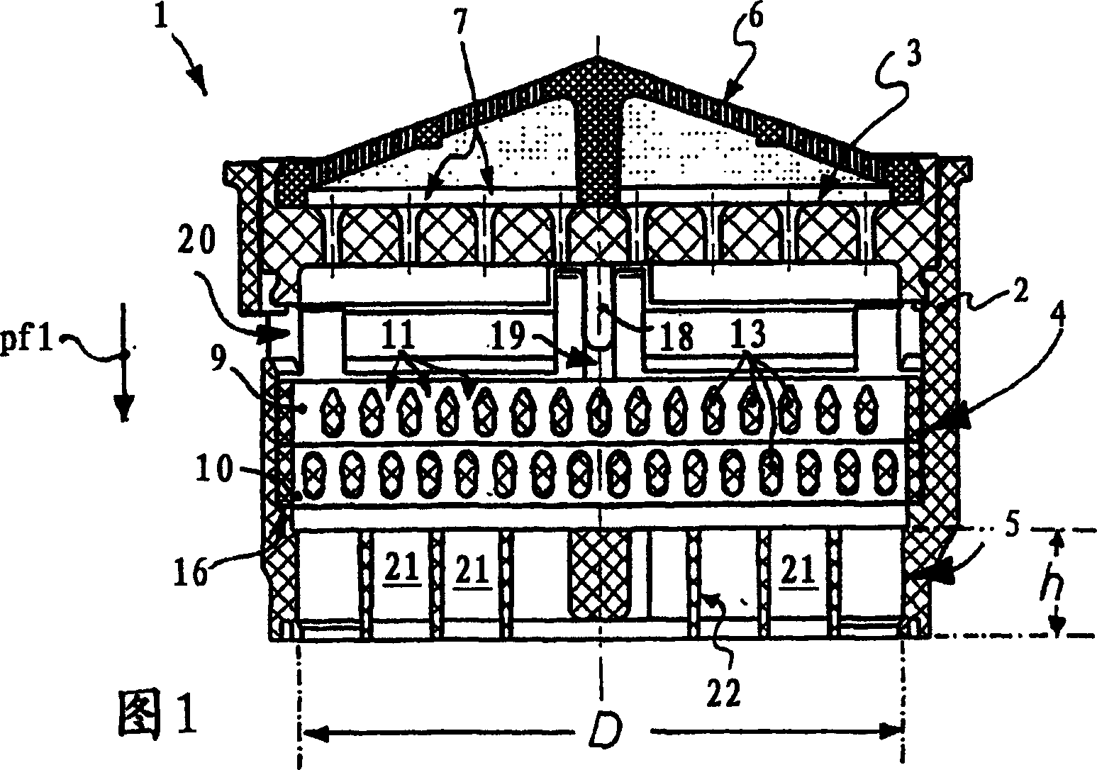
[0041] FIG. 1 shows a jet regulator 1 , which can be attached to a water outlet of a bathroom outlet fitting (not shown here) in order to generate a uniform, softly bubbling and non-splashing water flow.

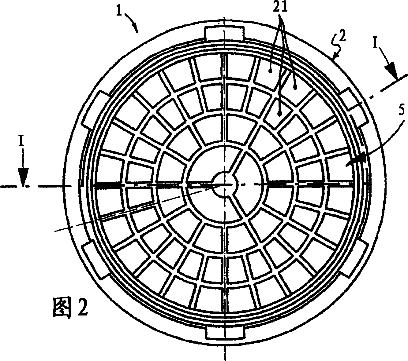
[0042] The jet regulator 1 has a sleeve-shaped jet regulator housing 2, inside which, in the flow direction Pf1, there is a water flow separator formed by an orifice 3, a subsequent jet regulator 4 and a water flow rectifier 5 at the water outlet. In order to be able to prevent dirty particles from inside the housing of the jet regulator 1 and to ensure its free-flowing operation, an additional screen 6 is arranged on the jet regulator 1 .

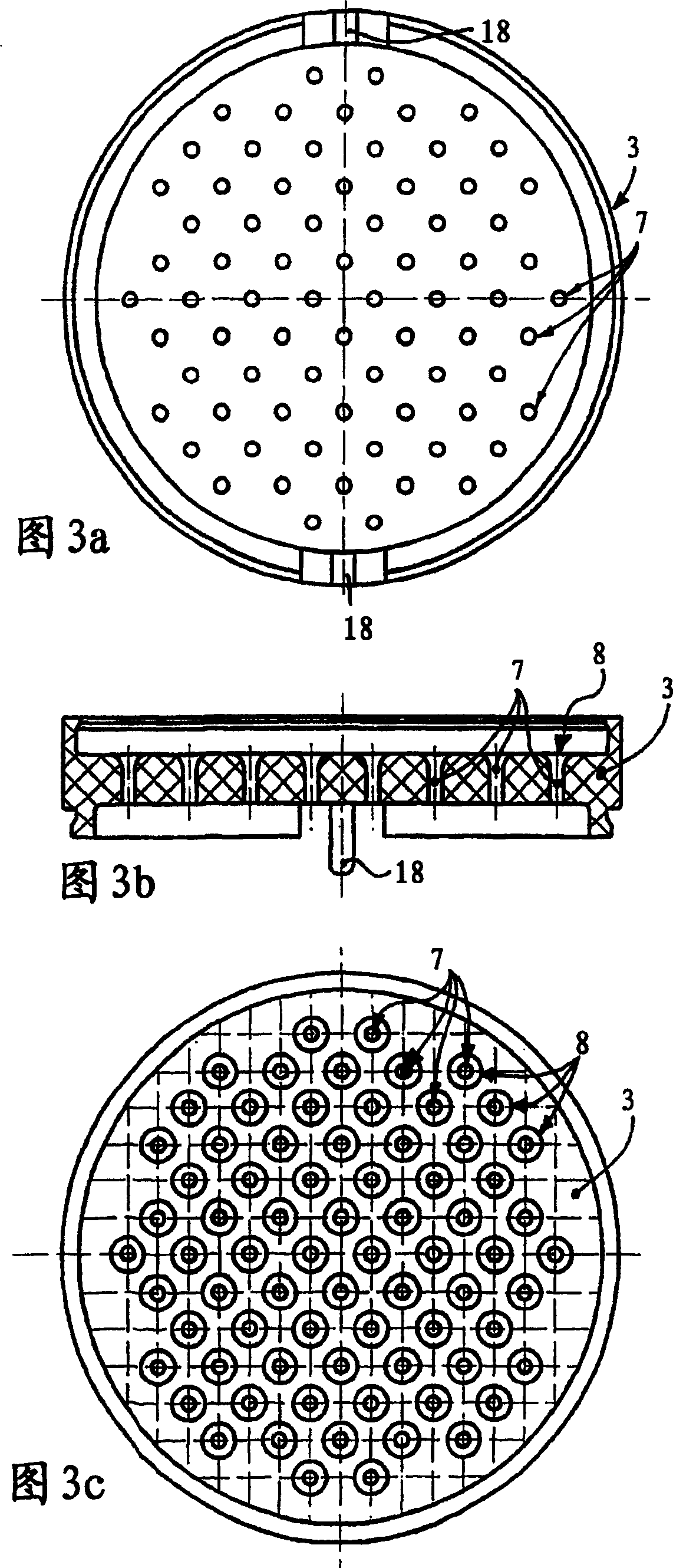
[0043] The orifice plate 3, whose plate surface is perpendicular to the flow direction Pf1, has a plurality of flow holes 7 spaced apart from each other, and the flow holes have funnel-shaped rounded inlet holes 8 at the water inlet respectively (see Fig. 3b, 3c).

[0044] The liquid flow to the jet regulator 1 is distributed into a plu...


PUM


Abstract

The invention relates to a jet regulator (1), comprising a jet regulator housing (2), within the interior of which a jet regulation device (4) is provided. According to the invention, such a jet regulator (1) can be produced at low cost, by means of simple conventional production techniques with simultaneous anti-scaling effect on the jet regulation device (4), whereby the jet regulation device (4) comprises several insertable components (9, 10), which may be inserted in series in the jet regulator housing (2) in the direction of flow (Pf1). Said insertable components (9, 10) comprise passage openings (11), which are unidirectionally defined and run across the cross-section of the passage and the passage openings (11) of adjacent insertable components (9, 10) are arranged offset to each other either in the circumferential direction of the jet regulator housing (2), or in the direction of flow (Pf1) of the jet regulator (1).

Description

technical field [0001] The invention relates to a jet regulator, which has a jet regulator housing, inside which a jet regulator device is arranged, the jet regulator device has a flow hole extending substantially on the flow cross section, the through hole in the jet regulation In the circumferential direction of the device housing or in the flow direction of the jet regulator, they are arranged offset from each other, wherein the jet regulator has at least one insert part with a flow hole. Background technique [0002] Jet regulators are known which have at least one metal mesh at the water outlet, wherein a plurality of perforated plates are arranged on the metal mesh to reduce the water flow (cf. US Pat. No. 4,119,276). However, such metal meshes as specified in US Pat. No. 4,119,276 are prone to fouling. [0003] A jet regulator is known from DE 196 42 055 C2, which can be mounted on the outlet nozzle of a bathroom outlet fitting in order to generate a bubbling, gentle...

Claims


Application Information

Patent Timeline
IPC IPC(8): E03C1/08
CPCE03C1/08
Inventor 赫尔曼·格雷瑟克里斯托弗·魏斯
Owner NEOPERL
Learn More