Energy-converting attraction-type power system

A technology of power plant and powdery materials, applied in the directions of transportation and packaging, conveying bulk materials, conveyors, etc., can solve the problems of low mixing ratio m, short conveying distance, low fan exhaust pressure, etc., to achieve convenient operation and maintenance, The effect of improved efficiency and high reliability

Inactive Publication Date: 2005-12-14
周树源
View PDF0 Cites 0 Cited by
  • Summary
  • Abstract
  • Description
  • Claims
  • Application Information

AI Technical Summary

Problems solved by technology

[0003] However, due to the characteristics of the fan, the exhaust pressure of the general fan is relatively low, most of which are 0.05MPa, although a few can reach 0.06MPa, but it has led to a rapid increase in power, and the noise is very large. In fact, this is rarely used. kind of status
Under normal exhaust pressure, the negative pressure capacity of the fan suction port can only reach 0.02MPa ~ 0.03MPa, which makes the mixing ratio m of the conveyed material low, generally only about 10 ~ 20, and the conveying distance is short , so that the advantages of negative pressure active reclaiming have not been brought into play
In addition, because the fan directly discharges the energy of the wind into the atmosphere during the negative pressure suction process, resulting in energy waste
The above-mentioned traditional transportation methods also have defects such as high noise, high energy consumption, and serious environmental pollution.
Although people can make some local improvements, they cannot fundamentally solve the above problems

Method used


Image

  • Energy-converting attraction-type power system
  • Energy-converting attraction-type power system
  • Energy-converting attraction-type power system

Examples


Embodiment Construction

[0017] The present invention will be described in more detail below in conjunction with the accompanying drawings and a preferred embodiment.

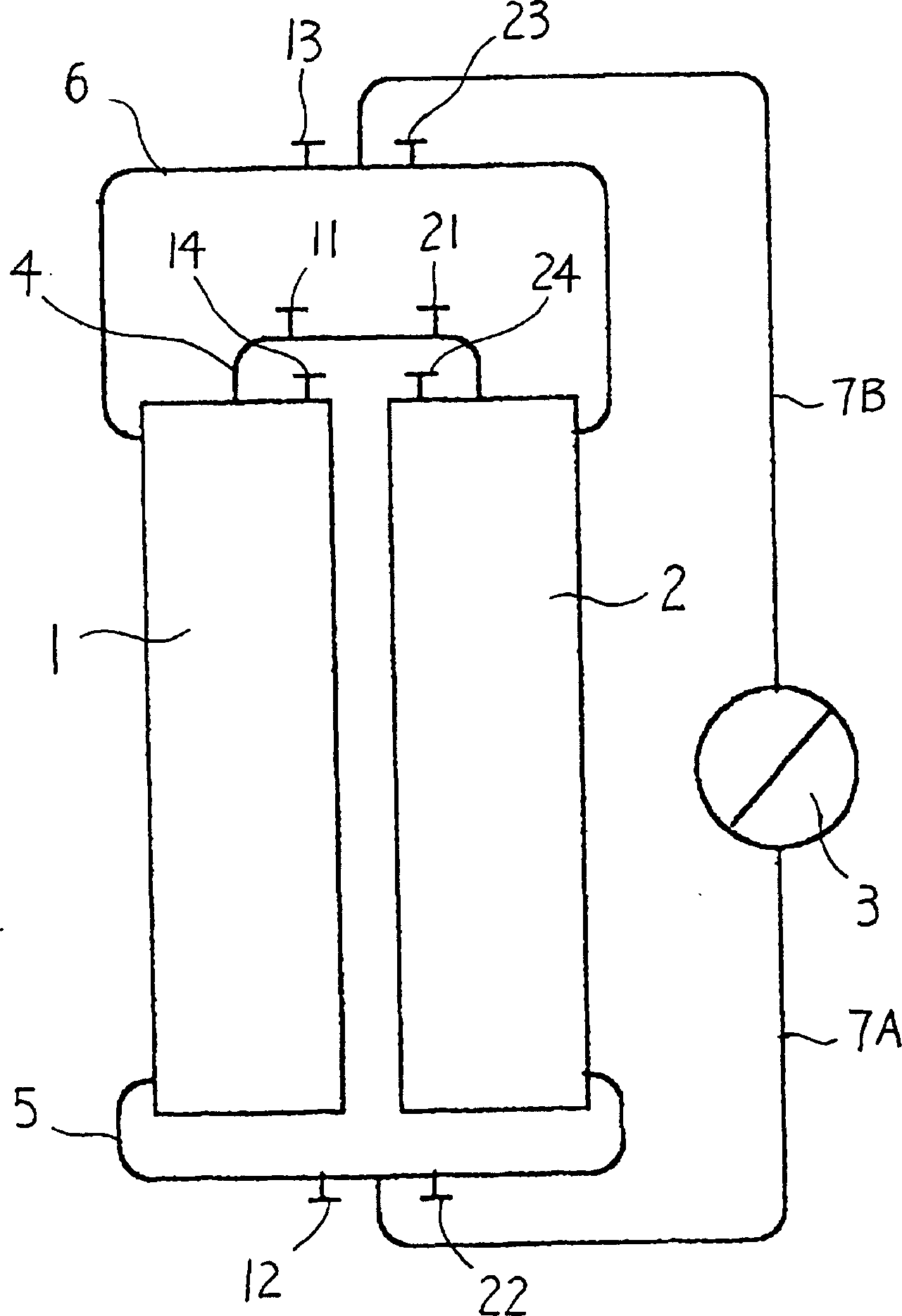
[0018] figure 1 Shows the basic structure of the energy-transfer suction power device of the present invention, as shown in the figure, the present invention is a kind of conversion of the liquid level energy by the work done by the liquid pump through the transduction tank without interruption, through this conversion to generate The negative pressure suction device required for conveying materials, the device includes two transduction tanks 1, 2 and a liquid pump 3, the two transduction tanks are closed cylinders made of metal, and the two transduction tanks pass through The pipelines 4, 5 and 6 are connected, and the liquid pump is connected with the two transducing tanks through the liquid inlet pipe 7A and the liquid outlet pipe 7B. Control valves 11 and 21 are installed on the connecting pipeline 4 of the two energy-transforming...


PUM


Abstract

An energy-transfer suction type power device, the device includes two energy-transfer tanks (1, 2) and a liquid pump (3), wherein the two energy-transfer tanks are connected through connecting pipes (4, 5, 6), The liquid pump is respectively connected to the connection pipe between the two transduction tanks through the liquid inlet pipe (7a) and the liquid outlet pipe (7b), and two control valves (11 , 21, 12, 22, 13, 23); An exhaust valve (14, 24) is also respectively housed on the two energy-transforming tank tank bodies. The two transducing tanks are alternately filled with liquid and empty when working, and the liquid level can be switched between the two states without interruption as the liquid pump (3) does work to generate high negative pressure. The device can be connected to a material conveying, loading and unloading or separating device through a pipeline (8). The invention has the characteristics of long conveying distance, low noise and energy consumption, no pollution, wide application range and the like.

Description

technical field [0001] The invention relates to a power device for conveying and separating granular or powdery materials, in particular to a power conversion suction power device which exchanges liquid potential energy through a transduction tank to generate negative pressure suction to perform work. Background technique [0002] In the practice of industrial production, a typical method of conveying granular and powdery materials is to use fans (including Roots blowers and centrifugal fans) to attract air, and then transport the granular and powdery materials to the At a certain position, through the air and material separator, the material is separated from the mixture with the air, so as to achieve the purpose of conveying the material. This traditional fan negative pressure suction method is widely used in the transportation of granular and powdery materials, such as bulk grain, bulk coal, bulk chemical fertilizer, bulk aluminum, cement, fly ash, etc. [0003] However,...

Claims


Application Information

Patent Timeline
Patent Type & Authority Patents(China)
IPC IPC(8): B65G53/24
Inventor 周树源孙龙兴
Owner 周树源
Why Eureka
Try Eureka