Manufacture of fluorescent lamp glass tubes

A glass tube and fluorescent lamp technology, applied in glass manufacturing equipment, discharge tube/lamp manufacturing, glass molding, etc., can solve the problems of high defective rate of lamps and weakened end walls, etc.

Inactive Publication Date: 2005-12-14
PANASONIC CORP
View PDF0 Cites 0 Cited by
  • Summary
  • Abstract
  • Description
  • Claims
  • Application Information

AI Technical Summary

Problems solved by technology

This fact is basically considered to weaken the mechanical strength of t...

Method used


Image

  • Manufacture of fluorescent lamp glass tubes
  • Manufacture of fluorescent lamp glass tubes
  • Manufacture of fluorescent lamp glass tubes

Examples


example 1

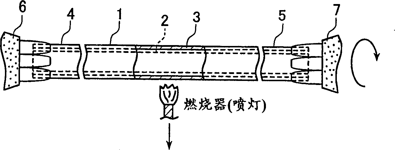
[0035] The following reference Figure 1A-1F A method of manufacturing a fluorescent lamp according to an embodiment of the present invention is explained.

[0036](1) A straight glass tube rotates around the tube axis, wherein the straight glass tube has, for example, a wall thickness of 0.85mm and an outer diameter of 16.5mm, and a fluorescent substance 2 is coated on the inner surface. Predetermined cutting portion 3 is heated, for example by torch heating ( Figure 1A ). Here, the ends 4 and 5 of the glass tube 1 are fixed by a pair of coaxial chucks 6 and 7 respectively, and so the glass (tube) is processed with great precision throughout the subsequent steps.

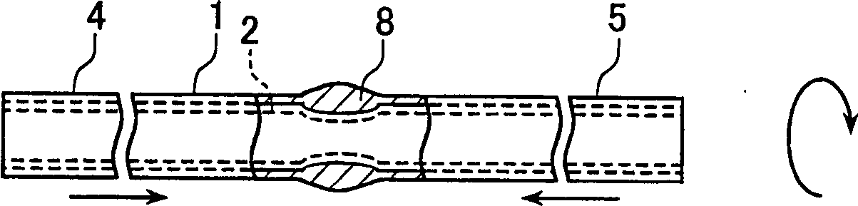
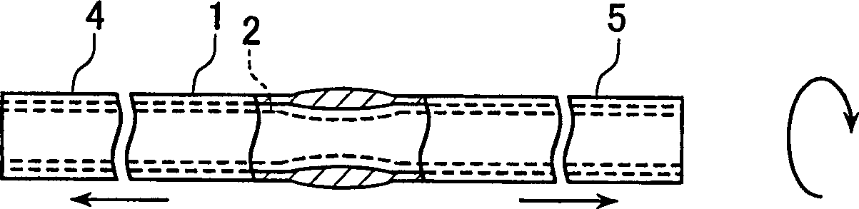
[0037] (2) When the predetermined cutting part 3 of the glass tube is heated and softened, while the glass tube is continuously heated by the torch, the ends of the glass tube 1 are respectively moved towards the predetermined cutting part 3 at a speed of 1.66 mm / 8. Move 2.5mm (by applying pressure in an inward...


PUM

PropertyMeasurementUnit
Thicknessaaaaaaaaaa

Abstract

The present invention provides a method of manufacturing a fluorescent lamp having an arc tube formed by connecting a plurality of glass tubes. According to this method, a straight glass tube held at both ends is rotated, a portion of the glass tube to be cut is heated and softened, and the heated glass tube is moved in a direction toward the cut portion to form a glass aggregate in the area of ​​the cut portion, and in the opposite direction. The glass tube is pulled apart in the direction and cut into two glass tubes with self-closing end walls. According to this method, the thickness of the end wall of the glass tube is thicker and more uniform compared with the conventional technology, and the mechanical strength is also improved. The rate of defective lamps due to cracks, leaks or damage in the end wall of the glass tube during the manufacturing process and distribution is thus reduced.

Description

technical field [0001] The invention relates to a method of manufacturing a fluorescent lamp. In particular, it relates to a method of cutting glass tubes for fluorescent lamps. Background technique [0002] In recent years, people's awareness of energy conservation has increased, and the use of compact fluorescent lamps has been proposed as an alternative energy-saving light source to replace inefficient light bulbs. [0003] For example, Japanese Patent JP4(1992)-58137A proposes a typical arc tube structure and its manufacturing method. In this manufacturing method, the steps of processing the glass tube are shown in Figure 7A ~7C: [0004] (A) The glass tube 30 coated with a fluorescent substance 31 on the inner surface is rotated around the tube axis, and while the glass tube is rotating, the glass wall near the center of the glass tube 30 is heated to a temperature slightly higher than The temperature of the softening temperature of the glass tube. [0005] (B) The...

Claims


Application Information

Patent Timeline
IPC IPC(8): C03B23/047C03B23/11C03B23/13C03B23/207C03B33/085H01J9/24
CPCC03B23/0473C03B23/11C03B23/13C03B23/207C03B33/085H01J9/247Y02P40/57
Inventor 尾贺俊喜齐藤胜白井耕三
Owner PANASONIC CORP
Why Eureka
Try Eureka