Screw compressor

A screw compressor, compressor technology, applied in mechanical equipment, machine/engine, liquid fuel engine, etc., can solve problems such as increasing the size of the cooler

Inactive Publication Date: 2005-12-21
HITACHI PLANT TECH LTD
View PDF1 Cites 1 Cited by
  • Summary
  • Abstract
  • Description
  • Claims
  • Application Information

AI Technical Summary

Problems solved by technology

Although the cooling performance of compressed air

Method used


Image

  • Screw compressor
  • Screw compressor
  • Screw compressor

Examples


Embodiment Construction

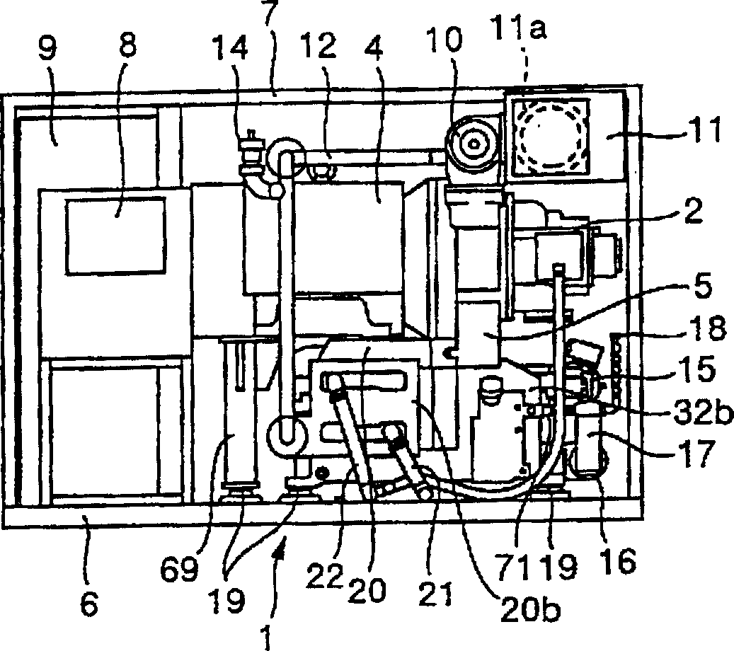
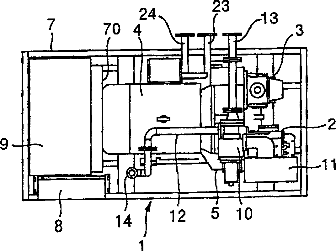
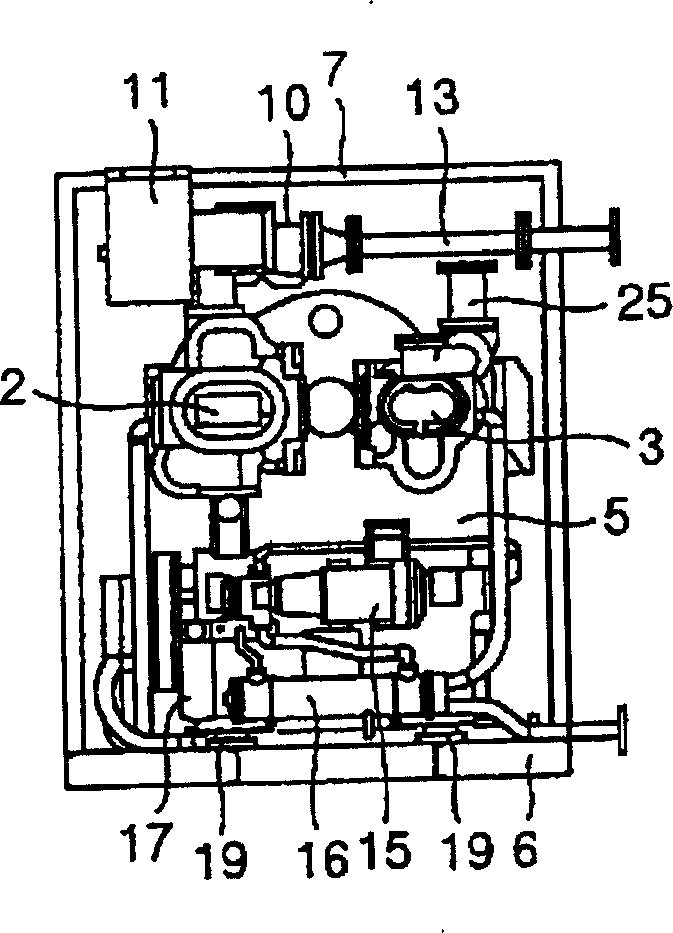
[0025] Next, an embodiment of the cartridge unit type screw compressor of the present invention will be described with reference to the drawings. Figure 1 to Figure 3 shows the appearance of the screw compressor of the present invention, Figure 4 and Figure 5 yes figure 1 Illustrative diagram of the working air flow in the screw compressor shown. Figure 15 After removing the soundproof cover figure 1 Perspective view of the shown cartridge unit screw compressor.

[0026] The screw compressor 1 of this embodiment is a two-stage compressor, including a low-pressure stage (first stage) compressor 2 and a high-pressure stage (second stage) compressor 3, and this screw compressor 1 is a so-called dry screw compressor, Of course, the meshing parts of its screw rotor do not require lubrication. The gas handled by this screw compressor is air. The discharge pressure of the screw compressor 1 (the discharge pressure of the second-stage compressor) is about 0.7-1.0 MPa (gauge ...


PUM


Abstract

A packaged unit screw compressor includes a low-pressure stage compressor and a high-pressure stage compressor. The raw power from the electric motor is transmitted to the two compressors through the speed increaser. The exhaust gas compressed and heated by the low-pressure stage compressor is cooled by the intercooler. The exhaust gas, which is compressed and heated by the high-pressure stage compressor to increase its temperature, is cooled by the aftercooler. The casing of the intercooler, the casing of the aftercooler and the casing of the speed increaser are integrated, thereby reducing the number of components. The cooler section formed by the intercooler and the aftercooler is separated from the speed-up case, thereby preventing heat generated by the compressed air from being transferred to the speed-up case.

Description

technical field [0001] The present invention relates to a screw compressor, in particular a screw compressor having two compressors, a high-pressure stage compressor and a low-pressure stage compressor. Background technique [0002] A conventional package-type screw compressor is disclosed in JP-A-6-101669. The packaged unit type screw compressor disclosed in this document, in order to facilitate observation and maintenance operation, reduce the assembly space, including minimizing the maintenance space, the speed-increasing gear and the main motor are installed on the base. Arrange the intercooler, aftercooler, oil cooler and coolant cooler in a direction perpendicular to the motor axis so that the air cooler kit can extend in the same direction. An operation panel with a maintenance display is installed on the front panel surface of the soundproof enclosure, and the door panel adopts a double-hinged structure. According to this structure, daily observations can be made i...

Claims


Application Information

Patent Timeline
IPC IPC(8): F04C18/16F04C23/00F04C29/00F04C29/02F04C29/04F04C29/12
CPCF04C23/00F04C23/001F04C29/005F04C29/023F04C29/04Y10T137/2521Y10T137/86381F04C18/16
Inventor 高桥一树鹤诚司谷山实三浦治雄
Owner HITACHI PLANT TECH LTD
Why Eureka
Try Eureka