Thin wall molded case member

A formwork member and thin-wall technology, which is applied to building members, building structures, floor slabs, etc., can solve the problems of increasing the cross-sectional size of the dense rib, inconvenient layout of formwork members, and increasing the amount of steel bars and concrete.

Inactive Publication Date: 2006-01-11
湖南邱则有专利战略策划有限公司
View PDF3 Cites 0 Cited by
  • Summary
  • Abstract
  • Description
  • Claims
  • Application Information

AI Technical Summary

Problems solved by technology

However, after being applied to dense ribbed floors, the formed dense ribs are all rectangular dense ribs, and their mechanical performance is not very reasonable. It is often necessary to increase the cross-sectional size of the dense ribs, increase the amount of steel bars and concrete, and increase the cost of the floor. At the same time, the layout of the formwork components is inconvenient, and the phenomenon of inconsistency in the width of the cast-in-place concrete ribs and the inconsistency of the thickness of the concrete protective layer between the formwork components is prone to occur, thereby affecting the overall quality and mechanical performance of the cast-in-place concrete hollow floor, increasing Construction difficulty, therefore, the development of a new type of thin-walled formwork components has been urgently needed

Method used


Image

  • Thin wall molded case member
  • Thin wall molded case member
  • Thin wall molded case member

Examples


Embodiment Construction

[0046] The present invention will be further described below in conjunction with the accompanying drawings and embodiments.

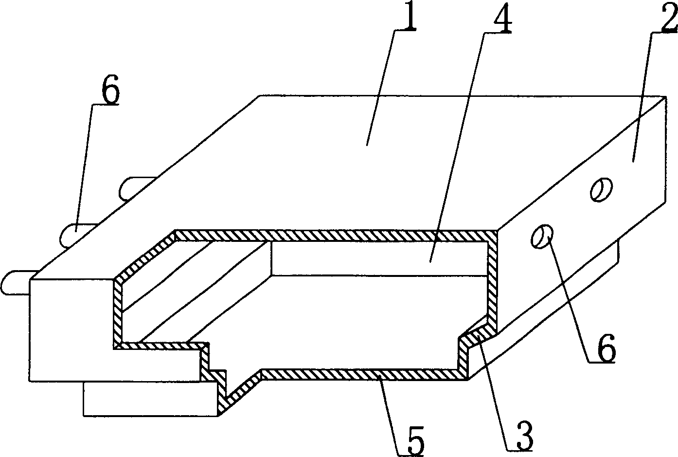
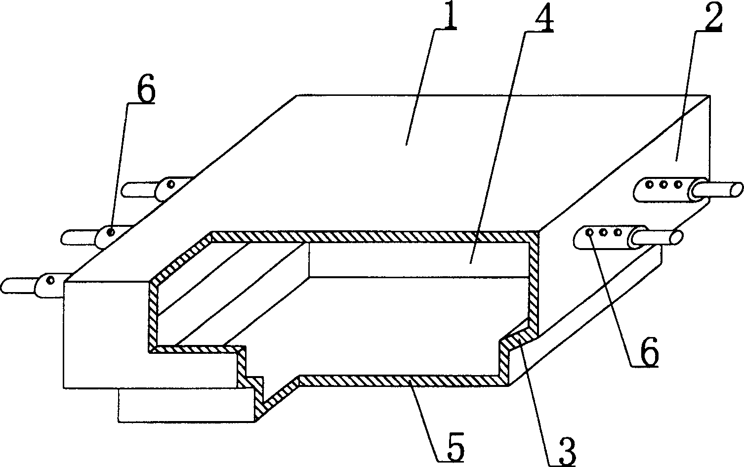
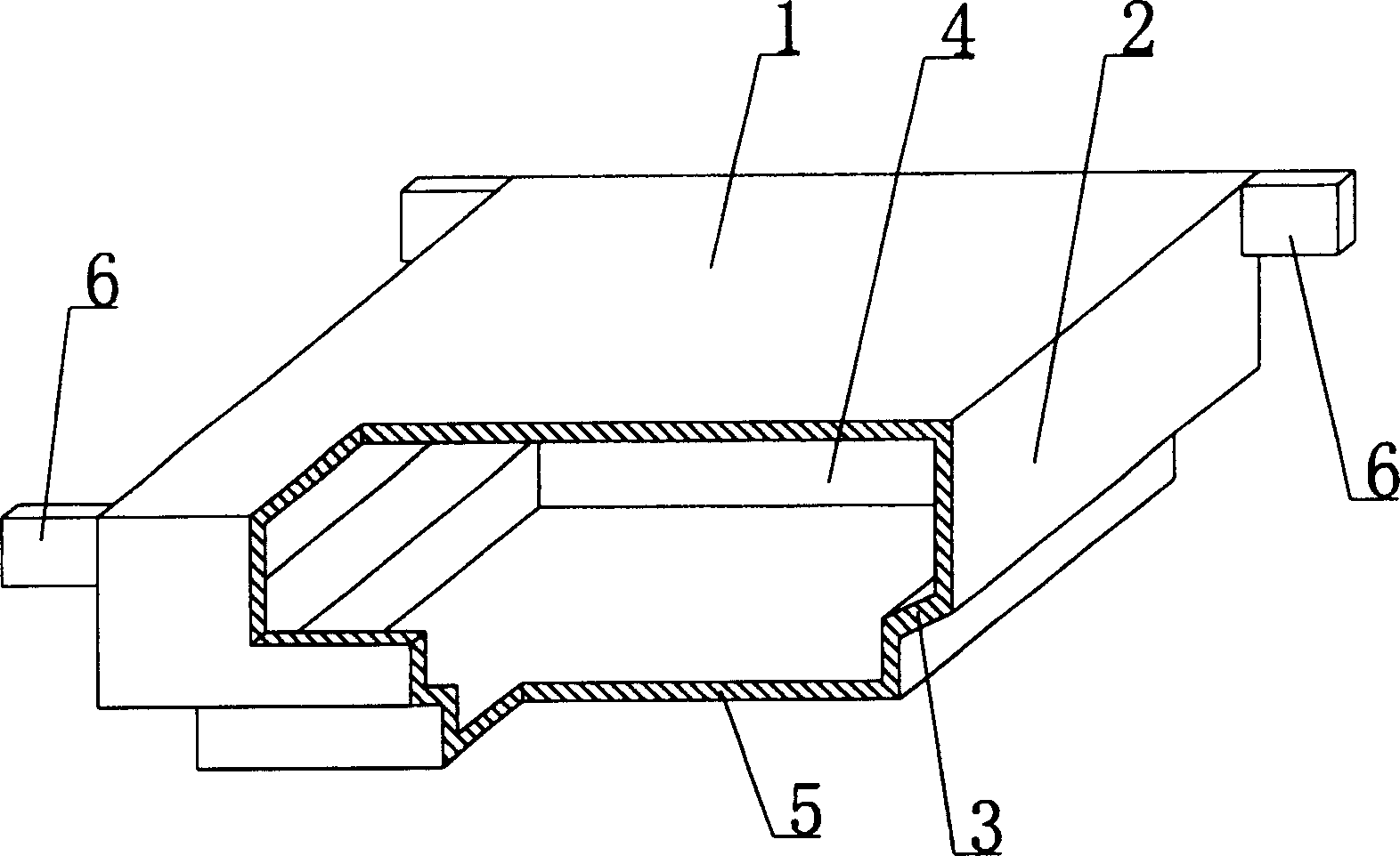
[0047] As shown in the accompanying drawings, the present invention includes an upper plate 1, surrounding side walls 2, and a lower bottom 3, and the upper plate 1, surrounding side walls 2, and lower bottom 3 form a cavity 4, which is characterized in that there is at least one on the lower bottom 3 The boss module 5 protruding from the lower bottom 3 is provided with at least one connecting part 6 on at least one surrounding side wall 2 . figure 1 It is a structural schematic diagram of Embodiment 1 of the present invention. In the accompanying drawings, 1 is the upper plate, 2 is the surrounding side wall, 3 is the lower bottom, 4 is the cavity, 5 is the boss module, 6 is the connecting part, in each drawing, the same numbers have the same description. Such as figure 1 As shown, the upper plate 1 , the side wall 2 , and the lower bottom 3 form a c...


PUM


Abstract

Disclosed is a thin-walled shuttering cavity component, which comprises an upper plate (1), a surrounding side-wall (2) and a lower bottom (3), the three parts are encircled to form a cavity (4), characterized in that at least one boss module (5) protrudes the lower bottom (3), and at least one connecting piece (6) is arranged on at least one surrounding side-wall (2). The shuttering component greatly improves the mechanical properties of the floor when being applied to the dense rib floor, reduces section size of the dense rib, reduces reinforcing steel bar and concrete consumption, and it is easy to lay and connect shuttering components, shift or displacement and unconformity of on-site casting concrete rib width and concrete protective layer thickness between shuttering components are avoided. The invention is suitable for on-site casting hollow floor, roof, soleplate, wall and empty bridge with on-site casting reinforced concrete or prestressed reinforced concrete, especially for hollow mushroom floor.

Description

(1) Technical field [0001] The present invention relates to a thin-walled formwork member. (2) Background technology [0002] At present, the cast-in-place concrete hollow floor is a widely used floor structure. The lightweight permanent tire molds filled in it include various hollow tubes and boxes, and the boxes are hollow or solid. For example, the patent No. ZL99249798.1, which the applicant applied for on November 29, 1999, is a utility model patent named "fiber-reinforced thin-walled member for reinforced concrete filling", which discloses a thin-walled formwork member, including an upper plate, The surrounding side walls, the lower bottom, and the upper plate, the surrounding side walls and the lower bottom form a polyhedral cavity. Another example is the patent No. ZL00203695.9 applied by Liang Jun, Shijiazhuang City, Hebei Province on February 23, 2000, and the name is called "combined concrete hidden rib floor cover plate" utility model patent, which discloses a f...

Claims


Application Information

Patent Timeline
Patent Type & Authority Patents(China)
IPC IPC(8): E04B5/36
Inventor 邱则有
Owner 湖南邱则有专利战略策划有限公司
Why Eureka
Try Eureka