Electronic circuit of switch power amplifier and method for switching said amplifier output stage

An electronic circuit and switching power technology, which is applied in the field of switching power amplifiers and the output stage of switching power amplifiers, can solve problems such as space increase, avoid current impact, reduce current kickback and voltage overshoot, and reduce required effect

Inactive Publication Date: 2006-01-11
NOKIA CORP
View PDF0 Cites 0 Cited by
  • Summary
  • Abstract
  • Description
  • Claims
  • Application Information

AI Technical Summary

Problems solved by technology

However, additional components also lead to an increase in the required space

Method used


Image

  • Electronic circuit of switch power amplifier and method for switching said amplifier output stage
  • Electronic circuit of switch power amplifier and method for switching said amplifier output stage
  • Electronic circuit of switch power amplifier and method for switching said amplifier output stage

Examples


Embodiment Construction

[0051] Figures 1 to 4 has been described above.

[0052] Figure 5 A division of the output stage of a first embodiment of a switching power amplifier according to the invention is shown.

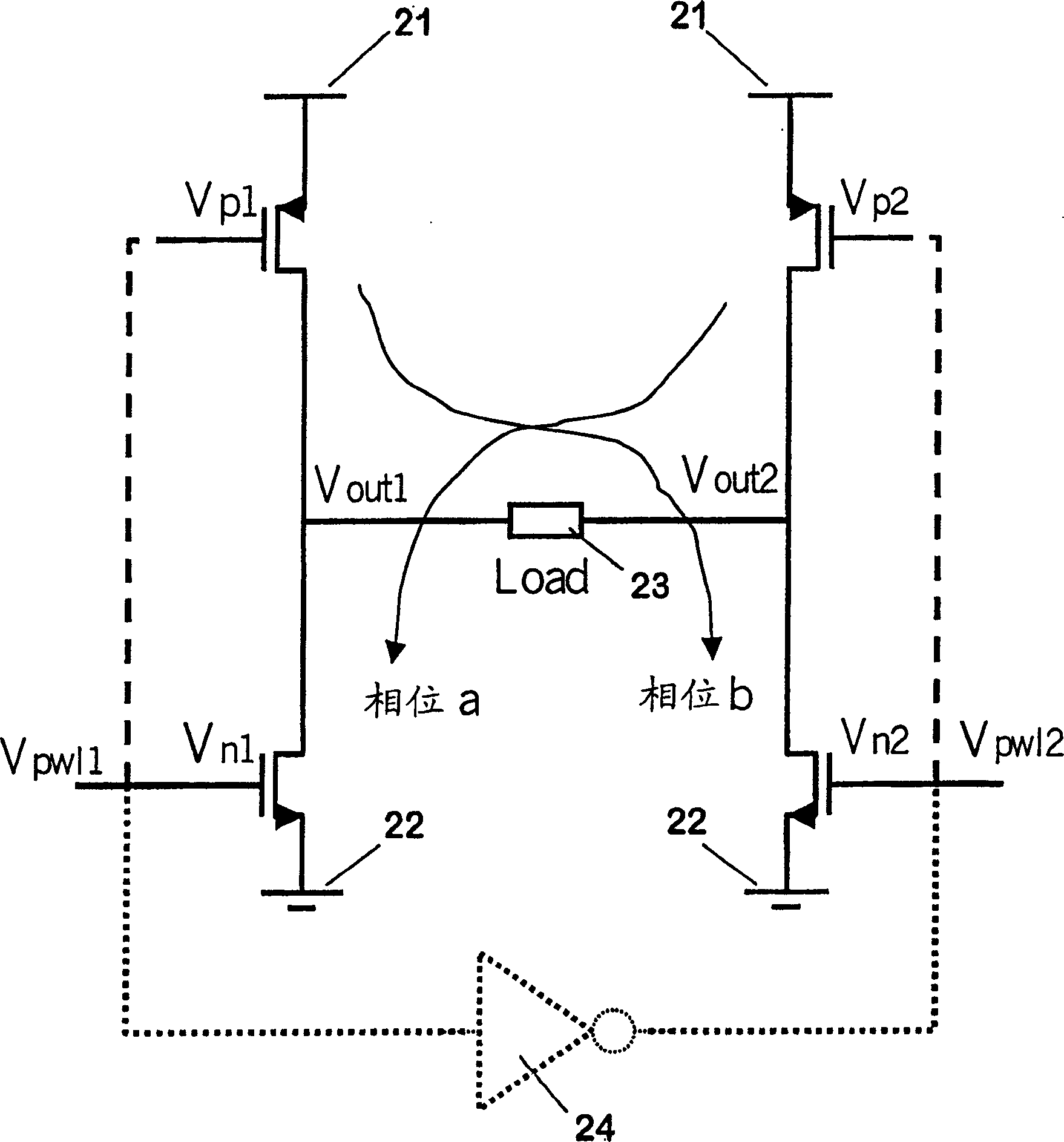
[0053] The output stage comprises a first switching stage 54 and a second switching stage 55 . Each switching stage 54 and 55 is a differential switching stage. Each switching stage can thus correspond to e.g. figure 2switching stage shown. A first output terminal of each switching stage 54 and 55 is connected to a first connection point of the load 53 , while a second output terminal of each switching stage 54 and 55 is connected to a second connection point of the load 53 . The two switching stages 54 and 55 are therefore connected in parallel to the load 53 .

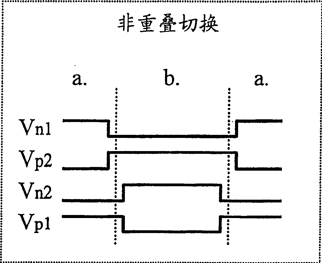
[0054] The first switching stage 54 is as described above with reference to Figure 3A shown by the clock signal for switching in non-overlapping mode. The second switching stage 55 is as described above with reference t...


PUM


Abstract

The invention relates to an electronic circuit for a switching power amplifier. In order to reduce problems during the transition stage when switching an output stage of the amplifier, it is proposed that the circuit comprises an output stage formed by at least two switching stages 54,55. Each of the switching stages 54,55 comprises at least two power switches and provides an output between the at least two power switches. Further, the switching stages 54,55 are connected in parallel to each other. The proposed circuit comprises in addition clocking means for switching the power switches, wherein the clocking means switch the power switches of at least one of the switching stages 55 in an overlapped mode and the power switches of at least one other of the switching stages 54 in a non-overlapped mode. The invention relates equally to a corresponding method.

Description

technical field [0001] The invention relates to electronic circuits for switching power amplifiers, switching power amplifiers, integrated circuits comprising electronic circuits for switching power amplifiers and devices comprising switching power amplifiers. The invention also relates to a method for switching an output stage of a switching power amplifier. Background technique [0002] It is already known in various fields, for example, in motor control, to use switching power amplifiers as switching RF (radio frequency) power amplifiers or class D audio amplifiers, where amplifiers are classified into classes A, B, C, D etc. according to their properties . Typically, the load of a switching amplifier is an electrical circuit that includes an inductive element such as a motor or a speaker. [0003] The main motivation for using switching power amplifiers is their high power efficiency. In portable devices, such as mobile phones, high power efficiency increases operatin...

Claims


Application Information

Patent Timeline
Patent Type & Authority Patents(China)
IPC IPC(8): H03F3/217
CPCH03F3/2171H03F3/2178
Inventor A·鲁哈T·罗特萨莱宁J·-P·特瓦罗托J·考皮宁
Owner NOKIA CORP
Why Eureka
Try Eureka