Optical head for scanning record carrier

A carrier and optical head technology, applied in optical recording head, recording/reproducing by optical method, system characterized by carrier structure, etc., can solve problems such as high cost of components and complex film lamination

Inactive Publication Date: 2006-02-15
CP MAHK JAPAN
View PDF0 Cites 0 Cited by
  • Summary
  • Abstract
  • Description
  • Claims
  • Application Information

AI Technical Summary

Problems solved by technology

[0004] A disadvantage of this known optical head is the relatively high cost of the components, caused by the presence of both phase structures and thin-film stacks
Furthermore, the thin-film stack is complex because it has to introduce a predetermined phase shift in the first radiation beam in order to achieve the same fraction of the radiation beam that has passed through the stack as the part that has passed through the phase structure. wave front

Method used


Image

  • Optical head for scanning record carrier
  • Optical head for scanning record carrier
  • Optical head for scanning record carrier

Examples


Embodiment Construction

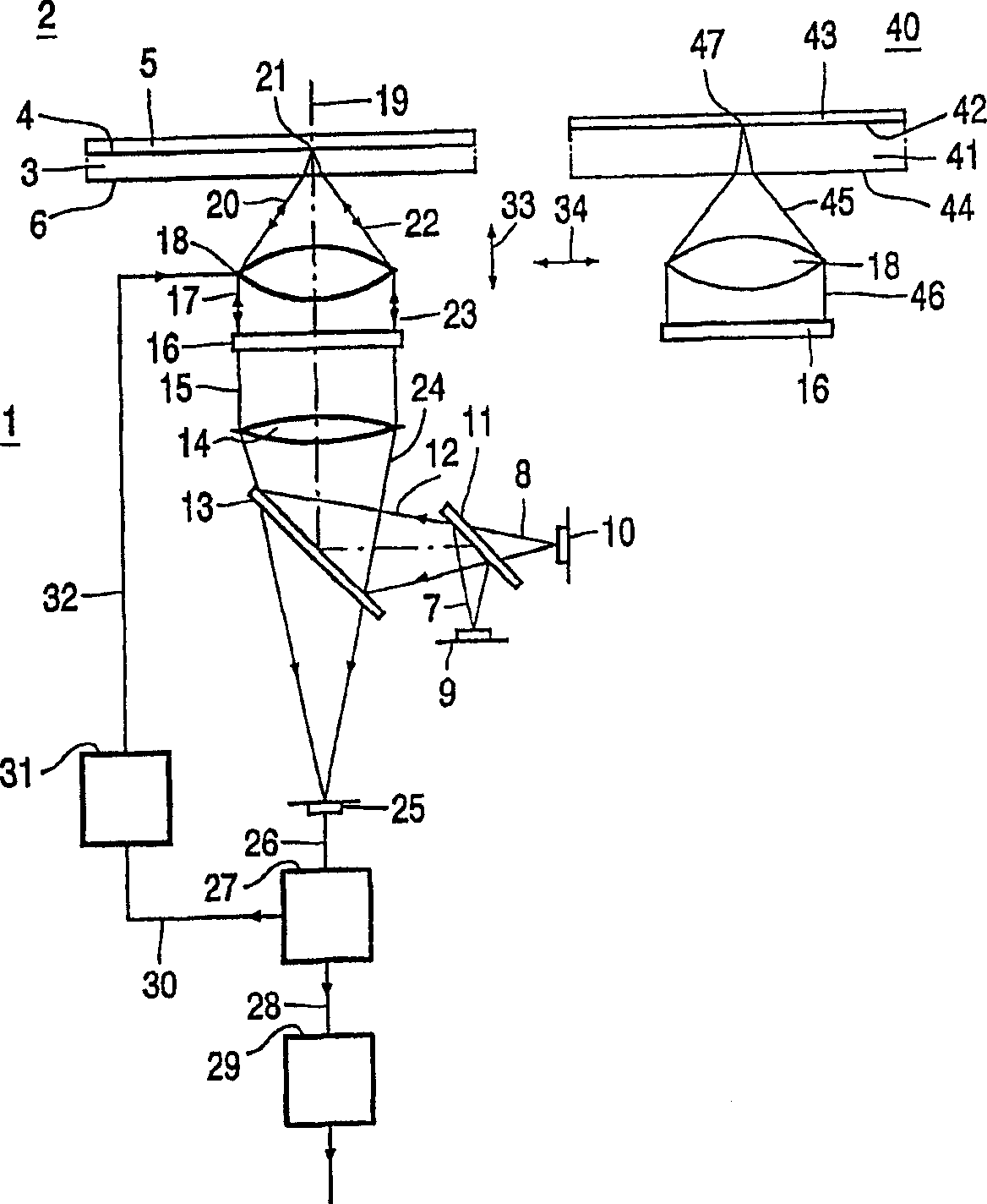
[0019] figure 1 A device 1 is shown for scanning an optical record carrier 2 of a first type and a record carrier 40 of a second type. In the illustrated embodiment, the first type is a DVD and the second type is a writable CD. The record carrier 2 comprises a transparent layer 3, on one side of which an information layer 4 is arranged. The side of the information layer facing away from the transparent layer is protected from environmental influences by a protective layer 5 . The side of the transparent layer facing the device is called the inlet face 6 . The transparent layer 3 acts as a substrate for the record carrier by providing mechanical support for the information layer. Alternatively, the transparent layer may have the sole function of protecting the information layer, while the mechanical support is provided by a layer on the other side of the information layer, for example by a protective layer 5 or by a further information layer and a transparent layer connected...


PUM


Abstract

A device for scanning a first and second type of optical record carriers (2; 40) generates a first and a second radiation beam for scanning the first and second type of record carriers, respectively, the first radiation beam having a first numerical aperture larger than the second numerical aperture of the second radiation beam. The device includes a non-periodic phase structure that does not affect the first radiation beam. The phase structure introduces an amount of spherical aberration in the second radiation beam for scanning the second type of record carriers for compensating the difference in spherical aberration required for scanning through the different thickness of the transparent layer (3; 41) of the first and second type of record carriers (2, 40). To reduce the amount of stray light on the detection system (25) from rays in the second radiation beam having a numerical aperture larger than the second numerical aperture, the phase grating introduces a discontinuity in the gradient of the wavefront deviation it introduces in the second radiation beam. The discontinuity allows spatial filtering in the plane of the detection system (25) of the desired and undesired rays of the second radiation beam.

Description

technical field [0001] The invention relates to an optical head for scanning different first and second types of record carriers. The invention also relates to a device for scanning two different types of optical record carriers, which device comprises the mentioned optical head. Both types of record carriers have an information layer and a transparent layer through which the radiation beam can scan the information layer. The thickness of the transparent layer is different for the two types of record carriers. The optical head comprises a radiation source for generating a first radiation beam having a first wavelength and a second radiation beam having a second different wavelength, the first radiation beam being adapted to scan a first type of record carrier, the second radiation beam The light beam is used to scan the second type of record carrier. The first radiation beam has a larger numerical aperture than the second radiation beam where it enters the record carrier. ...

Claims


Application Information

Patent Timeline
IPC IPC(8): G11B7/135G11B7/125G02B5/18G11B7/1353G11B7/00
CPCG11B7/1353G11B2007/13727G11B2007/0006G11B7/13922G02B5/1876G11B7/1392G11B7/1367G11B7/1275G11B7/139
Inventor J·E·德弗里斯B·H·W·亨德里克斯
Owner CP MAHK JAPAN
Why Eureka
Try Eureka