No-position sensor motor control device

A technology for control devices and motors, applied in motor control, AC motor control, control systems, etc., can solve problems such as estimated angle error, increased angle residual error, and difficulties

Inactive Publication Date: 2006-03-29
PANASONIC CORP
View PDF1 Cites 0 Cited by
  • Summary
  • Abstract
  • Description
  • Claims
  • Application Information

AI Technical Summary

Problems solved by technology

However, when driven by a waveform other than a sine wave (such as a trapezoidal wave or a square wave, etc.), there is a problem that, for example, the trapezoidal wave or square wave added to the stator winding of a motor is transformed into waveforms on the γ-axis and δ-axis, which is extremely difficult. difficulty
Therefore, there is a problem that if the method of prior art example 2 is used for waveforms other than sine waves, an error in the estimated angle will occur.
Therefore, there is a problem that the velocity-induced electromotive force constant Kv varies with temperature as described above, so the angle estimation error increases with changes in ambient temperature or with an increase in the internal temperature of the device, etc.
[0088] However, the disadvantage is that the induced voltage e is a value that changes with temperature, so adding the estimated induced voltage em that does not consider the temperature change increases the residual error of the estimated angle when the temperature changes

Method used


Image

  • No-position sensor motor control device
  • No-position sensor motor control device
  • No-position sensor motor control device

Examples


Embodiment 1

[0379] Hereinafter, the position sensorless motor control device of Embodiment 1 will be described.

[0380] The position sensorless motor controller of Embodiment 1 calculates the induced voltage value from the phase voltage equation of each phase of the stator winding, then calculates the deviation between the induced voltage value and the induced voltage reference value, and corrects the estimated angle θm so that the deviation converges to zero. Therefore, high-precision angle estimation can be realized with high resolution, angle estimation can be realized even when the phase voltage is saturated, and high-precision estimation can be realized even if motor constants such as induced voltage constants change.

[0381] In this document, the term "error" has the same meaning as "deviation".

[0382] First, the position sensorless motor control device of the first embodiment will be described.

[0383] ( figure 1 illustrate)

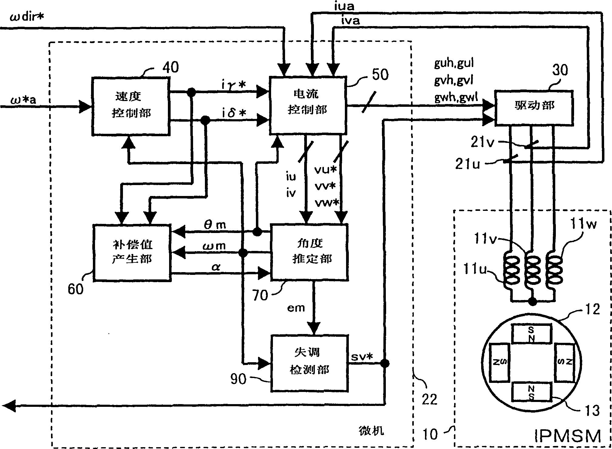
[0384] figure 1 It is a block diagram showin...

Embodiment 2

[0621] Next, a position sensorless motor control device according to Embodiment 2 of the present invention will be described. In the position sensorless motor control device of the first embodiment, the phase voltage values ​​vu, vv, vw are generated from the phase voltage command values ​​vu*, vv*, vw* generated by the current control unit 50 . In the position sensorless motor control device of Embodiment 2, a voltage sensor is added to directly detect the phase voltage. Therefore, high-precision angle estimation is realized with high resolution, angle estimation can be realized even when the phase voltage is saturated, and high-precision angle estimation can be realized even if the induced voltage constant changes.

[0622] First, the configuration of the position sensorless motor control device of the second embodiment will be described. Figure 11 It is a block diagram showing the configuration of the position sensorless motor control device according to the second embodi...

Embodiment 4

[0668] Next, a position sensorless motor control device in Embodiment 4 of the present invention will be described. The position sensorless motor control device of embodiment 1 uses the precise phase voltage equation to obtain the induced voltage value. On the other hand, the position sensorless motor control device of Embodiment 4 obtains the induced voltage value by using a simplified phase voltage equation, so the calculation time for angle estimation can be shortened.

[0669] ( Figure 15 illustrate)

[0670] First, a position sensorless motor control device according to Embodiment 4 will be described.

[0671] Figure 15 It is a block diagram showing the structure of the position sensorless motor control device in Embodiment 4, Figure 16 It is a block diagram showing the configuration of the angle estimation unit in the fourth embodiment. Only the microcomputer 422 is different from that of the first embodiment. The speed control unit 440, the current control unit...


PUM


Abstract

A position sensorless motor control apparatus is provided that achieves high resolution and high accuracy angle estimation, achieves angle estimation even in the presence of phase voltage saturation, and achieves high accuracy angle estimation even when a back electromotive force constant changes. An angle estimating unit which generates estimated rotor angle comprises: an estimation phase selecting unit for selecting an estimation phase designating the stator winding phase to be used for the generation of the estimated angle; a deviation generating unit for generating, based on the estimated angle and phase voltage value, a deviation relative to a model expressed by a phase voltage equation of the estimation phase; an angle correcting unit for correcting the estimated angle so that the deviation converges to zero; and an estimated coefficient value correcting unit for correcting an estimated coefficient value which is the estimated value of a coefficient in the phase voltage equation.

Description

technical field [0001] The invention relates to a position sensorless motor control device which rotates and drives the motor by estimating the rotor angle without using a position sensor. Specifically, it relates to a position sensorless motor control device that realizes high-precision angle estimation with high resolution, realizes angle estimation even when the phase voltage is saturated, and realizes high-precision angle estimation even when the induced voltage constant changes. Background technique [0002] Brushless motors without a mechanical commutation mechanism require electrical commutation according to the rotor angle. [0003] Existing motor control devices use position sensors such as Hall elements, resolvers, or optical encoders assembled on brushless motors to obtain rotor angle information. Therefore, the part of the position sensor increases the cost and also increases the size of the brushless motor. [0004] As a conventional position sensorless motor ...

Claims


Application Information

Patent Timeline
Patent Type & Authority Patents(China)
IPC IPC(8): H02P6/18H02P27/06H02P9/18
CPCH02P9/18H02P2203/05
Inventor 饭岛友邦楢崎和成田泽彻丸山幸纪
Owner PANASONIC CORP
Why Eureka
Try Eureka