
Gradient magnetic-field measuring method and MRI device

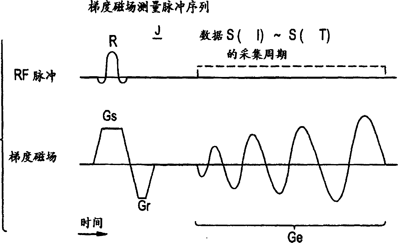
A technology of gradient magnetic field and measurement method, which is applied in the direction of measuring device, magnetic gradient measurement, magnetic performance measurement, etc., to achieve the effect of precise measurement

Inactive Publication Date: 2006-04-19
GE YOKOGAWA MEDICAL SYST LTD
View PDF0 Cites 0 Cited by
  • Summary
  • Abstract
  • Description
  • Claims
  • Application Information

AI Technical Summary

Problems solved by technology

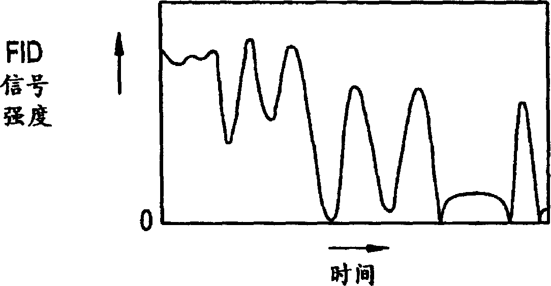
Basically the FID signal decreases exponentially with time, but there are many smaller minima due to the effect of the phase shift generated within the sample

Method used


Image

  • Gradient magnetic-field measuring method and MRI device
  • Gradient magnetic-field measuring method and MRI device
  • Gradient magnetic-field measuring method and MRI device

Examples


no. 1 example -

[0038] Figure 4 Shown is a block diagram of an MRI apparatus according to a first embodiment of the present invention.

[0039] In the MRI apparatus 100, the magnet assembly 1 has a hollow part (hole) to insert a target object, and around the hollow part, there are provided a constant intensity H to the target. 0 A permanent magnet 1p for a static magnetic field, a gradient magnetic field coil 1g for applying gradient pulses, a transmitting coil 1t for applying RF pulses to excite spins of atomic nuclei in the target, and a receiving coil 1r for detecting NMR signals from the target. The gradient magnetic field coil 1g, the transmitting coil 1t, and the receiving coil 1r are connected to the gradient magnetic field drive circuit 3, the RF power amplifier 4, and the preamplifier 5, respectively.

[0040] It should be noted that superconducting magnets or ordinary conducting magnets can be applied instead of permanent magnets.

[0041] Sequence memory circuit 8 operates gradie...

no. 2 example -

[0064] The gradient magnetic field measurement pulse sequence B shown in FIG. 9 can be used to measure smaller samples (for example, a sphere with a diameter of 10 cm).

[0065] In the gradient magnetic field measurement pulse sequence B shown in Figure 9, since the sample is small, it is not necessary to select the slice, so no slice selection pulse (G in Figure 6 e ). Furthermore, since no rephasing pulse is required (G in Figure 1 r ), the precoded pulse P k Consists of code pulses only.


PUM


Abstract

In order to accurately measure a gradient magnetic field, a pre-encoding pulse Pk is applied, data S(k, 1)-S(k, T) are collected from an FID signal while applying an encoding pulse Ge having a gradient waveform to be measured, and the above steps are repeated K times with the magnitude of the pre-encoding pulse Pk varied; data D(1,1)-D(1, T-1), D(2, 1)-D(2, T-1), . . . , D(K, 1)-D(K, T-1) having a phase difference DELTAphi as an angle are obtained from the collected data S(1,1)-S(1, T), S(2, 1)-S(2, T), . . . , S(K, 1)-S(K, T); data having corresponding magnitudes of the encoding pulse Ge are added to obtain added data d(1)-d(T-1); gradient magnetic field differences DELTAG(1)-DELTAG(T-1) are obtained from the added data d(1)-d(T-1); and the gradient magnetic field differences DELTAG(1)-DELTAG(T-1) are integrated to obtain a gradient magnetic field G(1)-G(T-1).

Description

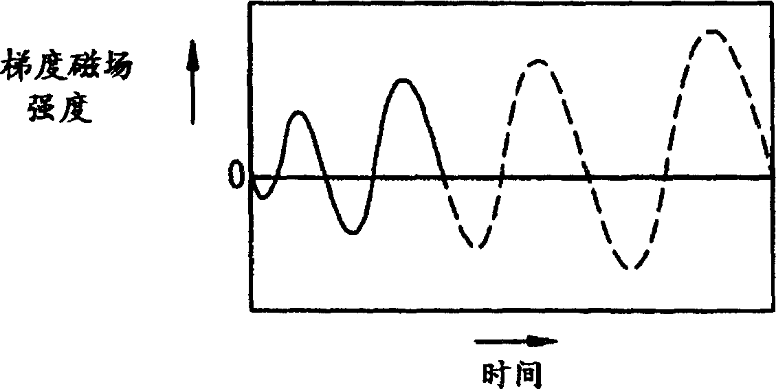
technical field [0001] The present invention relates to a gradient magnetic field measurement method and an MRI (Magnetic Resonance Imaging) apparatus, and more particularly, to a gradient magnetic field measurement method and an MRI apparatus capable of accurately measuring an actually applied gradient magnetic field. Background technique [0002] Fig. 1 shows the gradient magnetic field measurement method disclosed in the article entitled "Novel k-space Trajectory Measurement Technique" (Zhang et al., in Magnetic Resonance in Medicine, 39: 999-1004 (1998)). Figure of the applied gradient magnetic field measurement pulse sequence. [0003] Gradient magnetic field measurement pulse sequence J applies excitation RF pulse R and slice selection pulse G s , applying a complex phase pulse G r , and upon application of an encoding pulse G with a helical gradient waveform e While collecting data S(1)-S(T) from the FID signal. [0004] Next, data D(1)-D(T-1) having an angular ph...

Claims


Application Information

Patent Timeline
IPC IPC(8): G01R33/022G01R33/20A61B5/055G01R33/385G01R33/389G01R33/565
CPCG01R33/56518G01R33/3852A61B5/055
Inventor 宫本昭荣押尾晃一
Owner GE YOKOGAWA MEDICAL SYST LTD
Learn More