
Equipment with control unit, welding machine and welding torch

A technology for controlling equipment and welding machines, applied in welding equipment, arc welding equipment, metal processing equipment, etc., can solve problems affecting the flexibility of welding torches, and achieve the effect of reducing external influences and saving wires

Inactive Publication Date: 2006-04-26
FRONIUS INTERNATIONAL GMBH
View PDF0 Cites 0 Cited by
  • Summary
  • Abstract
  • Description
  • Claims
  • Application Information

AI Technical Summary

Problems solved by technology

The disadvantage here is that since the direct connection of the operating elements to the control unit requires a large number of wires, relatively thick hose packs are formed for connecting the welding machine to the welding torch, which impairs the flexibility when using the welding torch

Method used


Image

  • Equipment with control unit, welding machine and welding torch
  • Equipment with control unit, welding machine and welding torch
  • Equipment with control unit, welding machine and welding torch

Examples


Embodiment Construction

[0023] First of all, it should be clear that the same reference signs or the same reference numerals are used for the same parts in the shown embodiments, wherein the disclosure contained in the entire description can be transferred to the same reference signs or the same reference numerals. same part. Positional indications selected in the description, such as top, bottom, side, etc., refer to the direct description and the represented drawing, and when the position is changed, they are transferred to the new position as appropriate. Furthermore, individual features resulting from the exemplary embodiments shown can also represent independent solutions according to the invention.

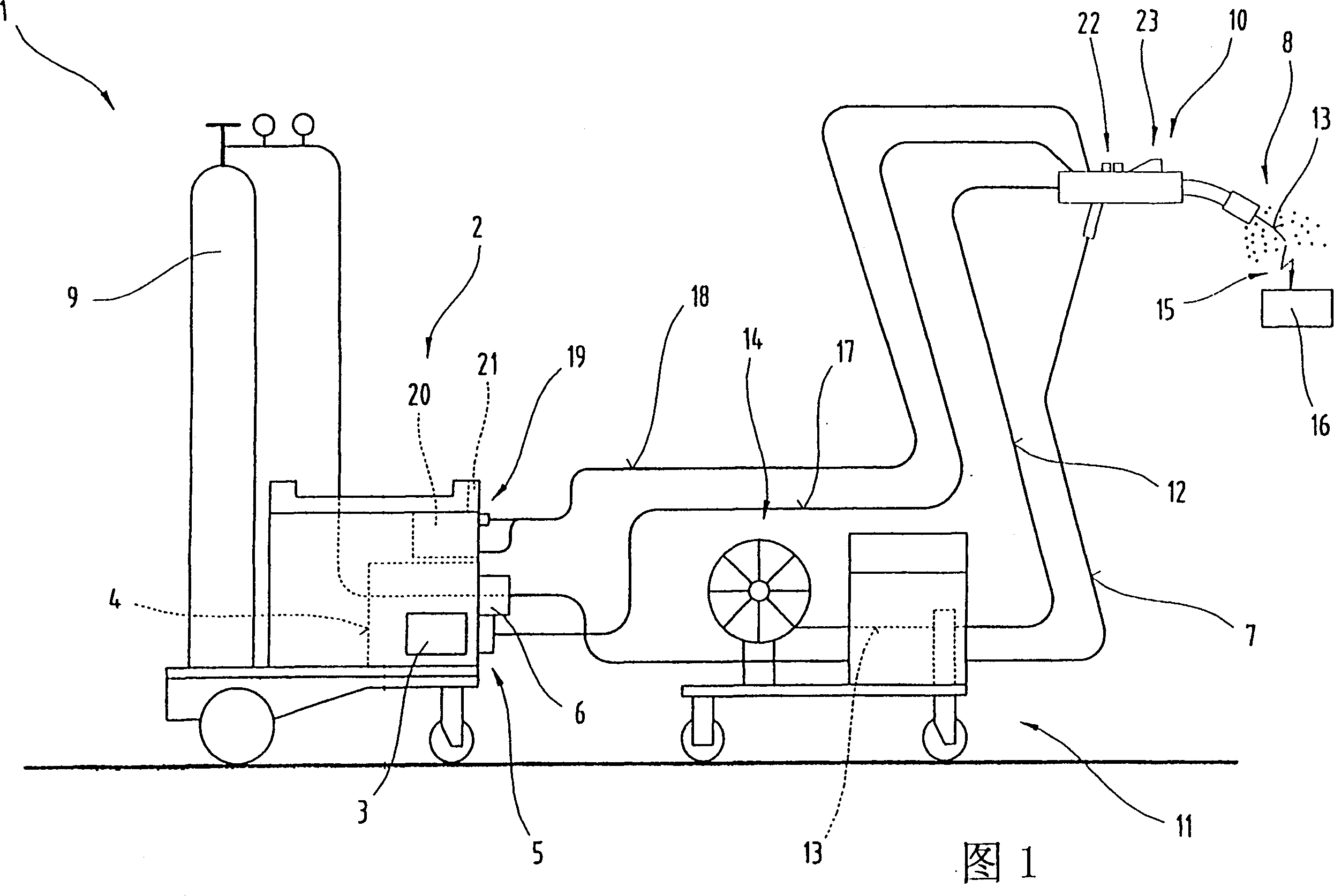
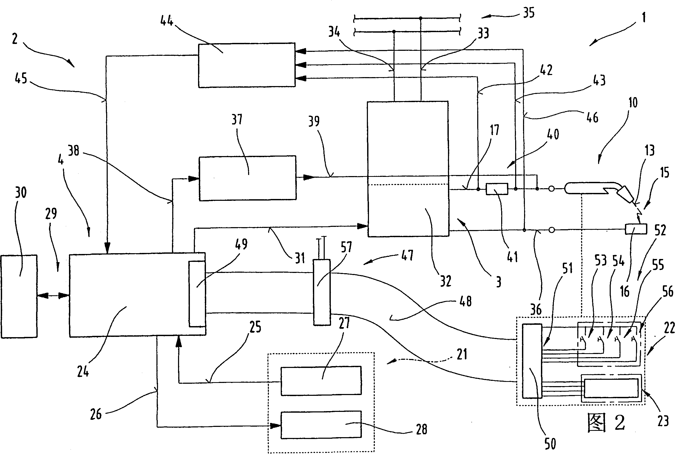
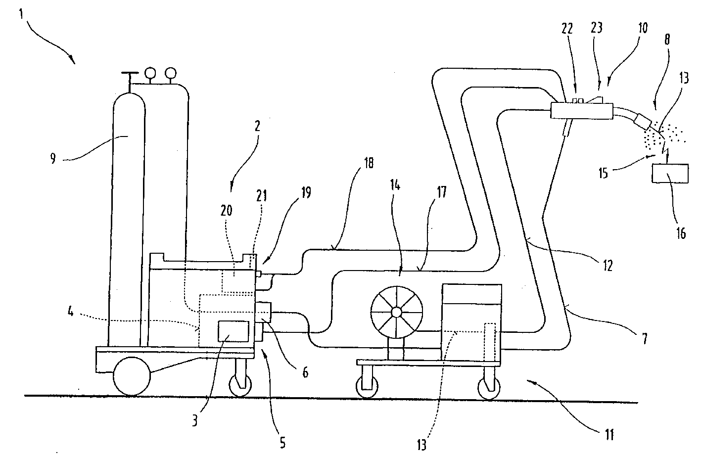
[0024] Figure 1 shows a welding machine 1, which is used for completely different welding methods, such as MIG / MAG welding or TIG welding. The welding machine 1 comprises a power source 2 with a power section 3 , a control unit 4 and a conversion element 5 associated with the power section 3 or th...


PUM


Abstract

The invention relates to a welding machine (1) or a control device (4) of welding equipment, comprising a welding torch (10) connected to the welding machine (1) through a connecting pipeline, wherein at least one input is provided on the welding torch (10) device (22) and / or a display device (23). The control device ( 4 ) is connected to a serial data bus, in particular a field bus, to which the welding torch ( 10 ) and / or the welding machine ( 1 ) and / or other components of the welding device are connected.

Description

technical field [0001] The invention relates to a device with a control device, a welding machine and a welding torch connected to the welding machine by a pipeline. Background technique [0002] Control devices for welding machines are known, in which an input device and a display device are provided in the welding torch. The individual operating elements of the input device or display device are directly connected via lines to the control unit of the welding machine, in particular a microprocessor controller, so that a control process can be initiated starting from the welding torch by actuating the operating elements. The changes or adjustments made are displayed on the display device on the welding torch, so that the user can read these changes on the display device at any time. The disadvantage here is that, since the direct connection of the operating elements to the control unit requires a large number of wires, a relatively thick hose pack is formed for connecting t...

Claims


Application Information

Patent Timeline
IPC IPC(8): B23K9/10
CPCB23K9/1062
Inventor 赫尔穆特·弗里德尔弗兰茨·尼德勒德
Owner FRONIUS INTERNATIONAL GMBH
Learn More