Moving-iron electromagnet

An electromagnet and moving iron technology, applied in the direction of electromagnets and electromagnets with armatures, can solve the problems of large mass of the movable part of the armature, high requirements for winding coils of the moving coil, and cramped space for the armature, etc., to achieve good control High performance, compact structure, heat reduction effect

Inactive Publication Date: 2006-06-07
ZHEJIANG UNIV
View PDF0 Cites 0 Cited by
  • Summary
  • Abstract
  • Description
  • Claims
  • Application Information

AI Technical Summary

Problems solved by technology

[0002] The moving coil electromagnet can reach a higher frequency, but this kind of electromagnet has a large volume and needs to be equipped with a special heat dissipation system, which consumes a lot of energy; in order to achieve good linearity, the distribution of the stable magnetic field and the winding requirements of the moving coil high
Most of the moving iron high-frequency electromagnets are simply driven, with switching properties and poor control characteristics; the electromagnets of the general bridge magnetic circuit are mostly two control coils, plus springs and output parts, making the space around the armature very cramped , and the mass of the movable part of the armature is also relatively large

Method used


Image

  • Moving-iron electromagnet
  • Moving-iron electromagnet
  • Moving-iron electromagnet

Examples


Embodiment Construction

[0023] The present invention will be further described below in conjunction with drawings and embodiments.

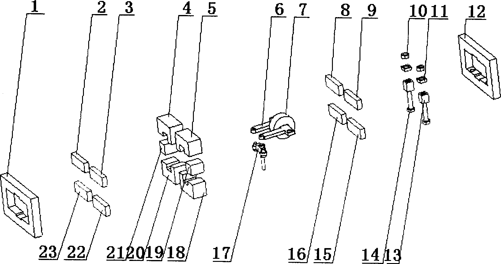
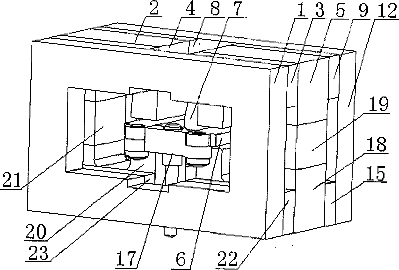
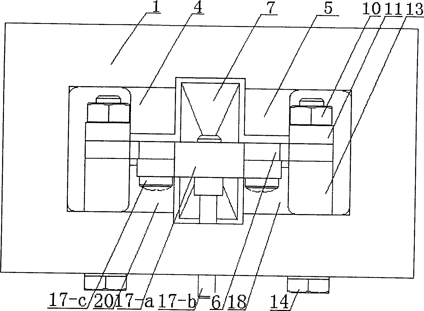
[0024] like Figure 1 to Figure 7 As shown, the present invention includes the first layer of the magnetically conductive plate 1 in turn, and the middle hollow is arranged with a pair of corners with magnetically conductive blocks 2, 22 and the other diagonally with a second layer of non-magnetically conductive blocks 3, 23, One side hollowed out in the middle is made up of yoke 4, magnetic steel 21, yoke 20 and the other side is made up of another yoke 5, magnetic steel 19, yoke 18. The magnetic permeable blocks 8, 15 and the fourth layer of the magnetic permeable blocks 9, 16 are arranged diagonally, and the fifth layer of the other magnetic permeable plate 12 is combined. The hollowed-out space in the middle formed by the combination of five floors is equipped with such Figure 11 As shown in the "Π" shaped armature, the middle arm 6-c of the armature is equipped ...


PUM


Abstract

The invention discloses a moving iron electromagnet. The permanent magnet is used to generate the excitation magnetic field, which greatly reduces the energy consumption of the system, reduces the calorific value of the system, and improves the system performance; uses the full bridge magnetic circuit to realize the accurate control of the movement of the moving iron, and achieves good control performance; adopts "∏ "Shaped armature, the middle arm of the armature and the control coil do not move during the movement, and the side arm of the armature is connected by light materials to lead out the output, which greatly reduces the mass of the movable part and is conducive to the increase of frequency; the armature on both sides of the armature The effect of the high stiffness spring is conducive to the reduction of hysteresis; there is only one control coil, and the control coil and the output part are separated, the space around the armature is spacious, the structure is simplified, and it is beneficial to reduce the volume of the entire electromagnet; it has a compact structure, The advantages of small size, high efficiency, energy saving, and large power-to-weight ratio. The invention can be applied to systems requiring high-frequency electromagnetic drive devices such as electronic engraving machines.

Description

technical field [0001] The invention relates to a high-frequency electric-mechanical conversion mechanism used in an electromagnetic drive system, in particular to a moving iron electromagnet. Background technique [0002] The moving coil electromagnet can reach a higher frequency, but this kind of electromagnet has a large volume and needs to be equipped with a special heat dissipation system, which consumes a lot of energy; in order to achieve good linearity, the distribution of the stable magnetic field and the winding requirements of the moving coil high. Most of the moving iron high-frequency electromagnets are simply driven, with switching properties and poor control characteristics; the electromagnets of the general bridge magnetic circuit are mostly two control coils, plus springs and output parts, making the space around the armature very cramped , At the same time, the mass of the movable part of the armature is also relatively large. Contents of the invention ...

Claims


Application Information

Patent Timeline
Patent Type & Authority Patents(China)
IPC IPC(8): H01F7/08H01F7/06
Inventor 丁凡张策方平李其朋王洁
Owner ZHEJIANG UNIV
Why Eureka
Try Eureka