Electric aircraft

An aircraft and electric technology, applied in the field of aviation aircraft, can solve problems such as propeller failure, loud noise, and high-altitude air pollution, and achieve good flight stability, avoid complex structures, and low flight noise

Inactive Publication Date: 2006-06-21
钟志华
View PDF0 Cites 0 Cited by
  • Summary
  • Abstract
  • Description
  • Claims
  • Application Information

AI Technical Summary

Problems solved by technology

But this kind of helicopter installs two sets of propellers on the same central power shaft. In order to ensure that the rotation directions of the two sets of propellers are opposite, the structure of the transmission device is very complicated. The biggest disadvantage of the above two aircraft is that the propellers rely on a single Driven by the power shaft, the safety factor is low, because if any of the power shaft, drive, transmission or engine fails, the propeller will not work normally, causing the aircraft to crash
Moreover, the existing helicopters all use fuel engines, which are not only noisy, but also emit harmful exhaust gases, cause high-altitude air pollution, and destroy the ozone layer.
[0003] Above-mentioned two kinds of helicopters all can carry out long-distance horizontal movement (flight), and its structure is complicated, and cost is high, and maintenance cost is big, and the cost of each flight is high, and according to the difference of aviation use, in many occasions, we only need A fixed-point aircraft capable of carrying people and objects that can fly vertically and hover stably in the air

Method used


Image

  • Electric aircraft
  • Electric aircraft
  • Electric aircraft

Examples


Embodiment Construction

[0018] Drawing No.:

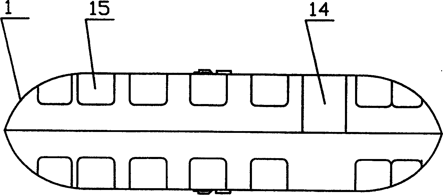
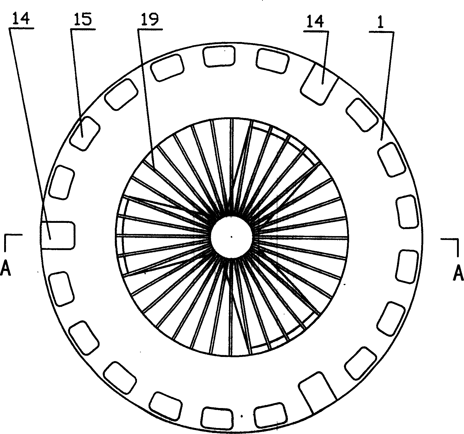
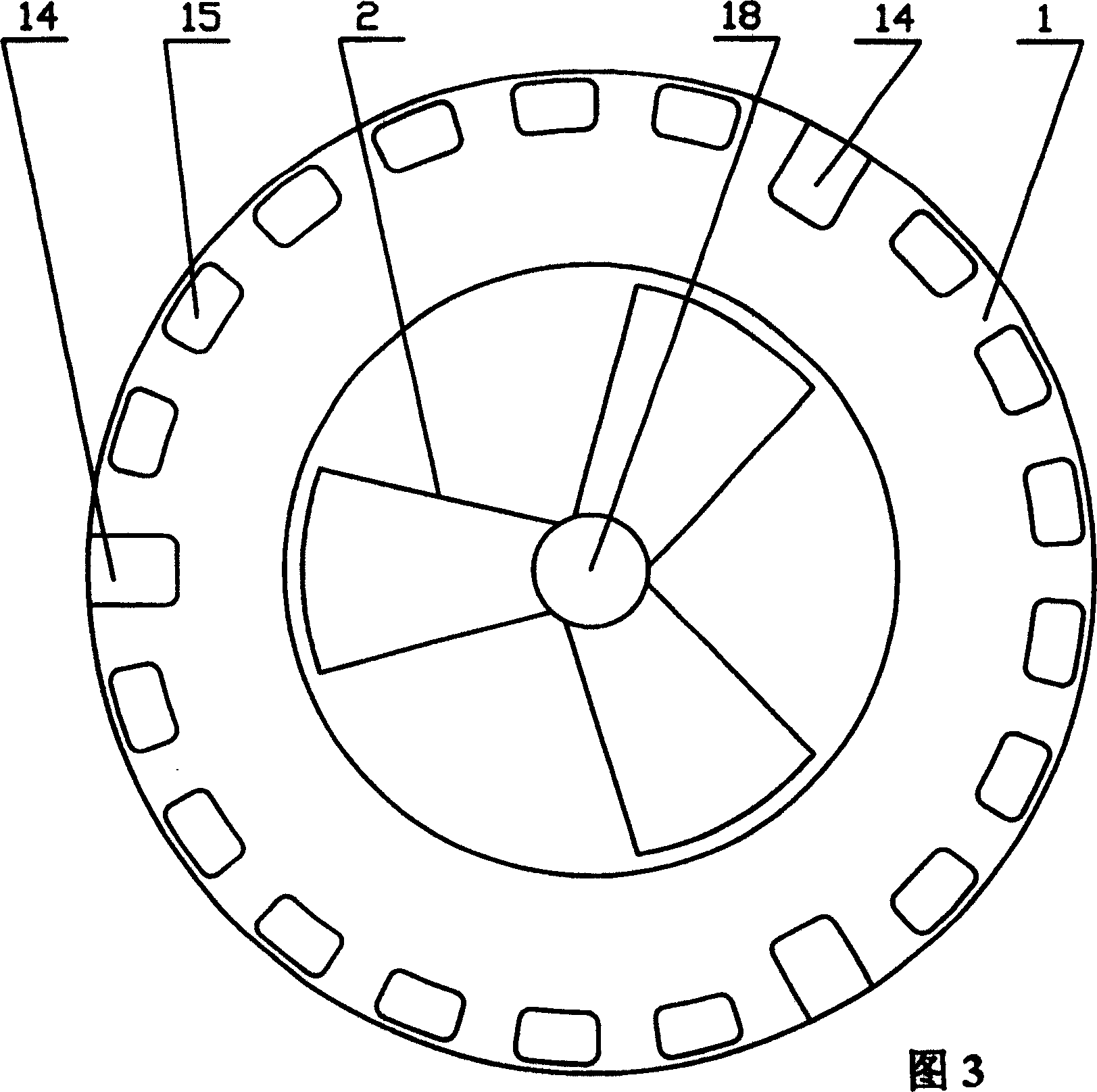
[0019] 1. Ring shell 2. Upper flying wing group 3. Lower flying wing group

[0020] 4A. Upper circular guide rail (the upper guide rail in the upper circular guide rail)

[0021] 4B. Upper circular guide rail (the lower guide rail in the upper circular guide rail)

[0022] 5A. Lower circular guide rail (the upper guide rail in the lower circular guide rail)

[0023] 5B. Lower circular guide rail (the lower guide rail in the lower circular guide rail)

[0024] 6. Passenger compartment 7. High-speed motor 8. Main shaft 9. Roller

[0025] 10. Central shaft 11. Bearing 12A. Conductive ring 12B. Conductive ring

[0026] 13A. Conductive ring 13B. Conductive ring 14. Door 15. Window

[0027] 16. Passenger 17. Channel 18. Cover 19. Spokes

[0028] 20. Cover 21. Spokes 22. Power cord 23. Power cord

[0029] 24. Connecting plate 25. Bolt 26. Longitudinal I-shaped rib

[0030] 27. Horizontal I-shaped rib 28. Skin 29. Bearing

[0031] 30A. Brush 30B. Brush 3...


PUM


Abstract

An electric aircraft, the central space of the annular housing is equipped with upper and lower flying wing groups, the inner side of the annular housing is equipped with upper and lower annular guide rails, the outer side of the annular housing is the passenger compartment, and the upper and lower flying wing groups have There are multiple wings, and several high-speed motors are installed in each wing. The main shaft of the high-speed motor is equipped with a roller. When driving the wings to make a circular motion along the guide rail, the upper and lower flying wing groups are respectively connected to the central shaft through bearings, and the central shaft is equipped with four conductive rings, and each wing in the upper and lower flying wing groups Brushes are respectively installed at the positions; the conductive rings are respectively connected to the power lines, and the power lines are connected to the ground power supply. The electric aircraft of the invention has the advantages of simple structure, low cost, good flight stability, high safety factor, vertical take-off and landing, stable hovering in the air, no emission of harmful gas, and low flight noise.

Description

technical field [0001] The invention belongs to the technical field of aviation aircraft, in particular to a rotorcraft. Background technique [0002] Most of the existing vertically liftable aircraft such as helicopters use a single propeller (rotary wing). The disadvantage is that the stability is poor, and the tail rotor needs to be used to balance the counter torque. There are very few helicopters that use dual propellers (dual rotors), and there is no need to use the tail rotor to balance the anti-torque during flight. It is less affected by the wind and flies smoothly. But this kind of helicopter installs two sets of propellers on the same central power shaft. In order to ensure that the rotation directions of the two sets of propellers are opposite, the structure of the transmission device is very complicated. The biggest disadvantage of the above two aircraft is that the propellers rely on a single Driven by the power shaft, the safety factor is low, because if any ...

Claims


Application Information

Patent Timeline
Patent Type & Authority Patents(China)
IPC IPC(8): B64C39/06B64C39/00
Inventor 钟志华
Owner 钟志华
Why Eureka
Try Eureka