Cavity body structure of microwave oven

A microwave oven and cavity technology, applied in the field of microwave ovens, can solve problems such as difficult maintenance work, and achieve the effects of easy installation of accessories, minimized area, and easy maintenance

Inactive Publication Date: 2006-07-19
LG ELECTRONICS (TIANJIN) APPLIANCES CO LTD
View PDF0 Cites 0 Cited by
  • Summary
  • Abstract
  • Description
  • Claims
  • Application Information

AI Technical Summary

Problems solved by technology

Therefore, the snap lock installation structure is arranged in a narrow space, making future maintenance work difficult

Method used


Image

  • Cavity body structure of microwave oven
  • Cavity body structure of microwave oven
  • Cavity body structure of microwave oven

Examples


Embodiment Construction

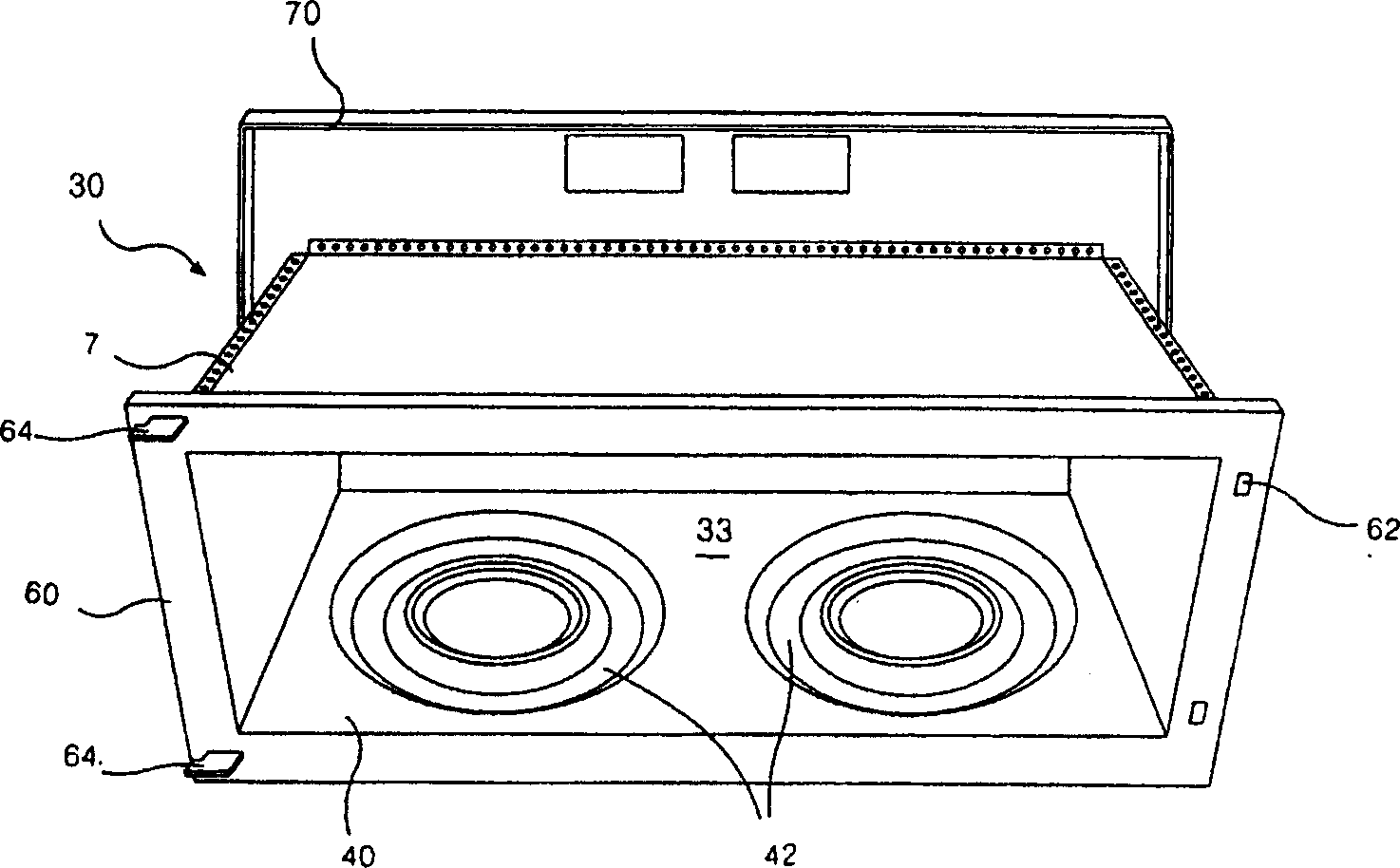
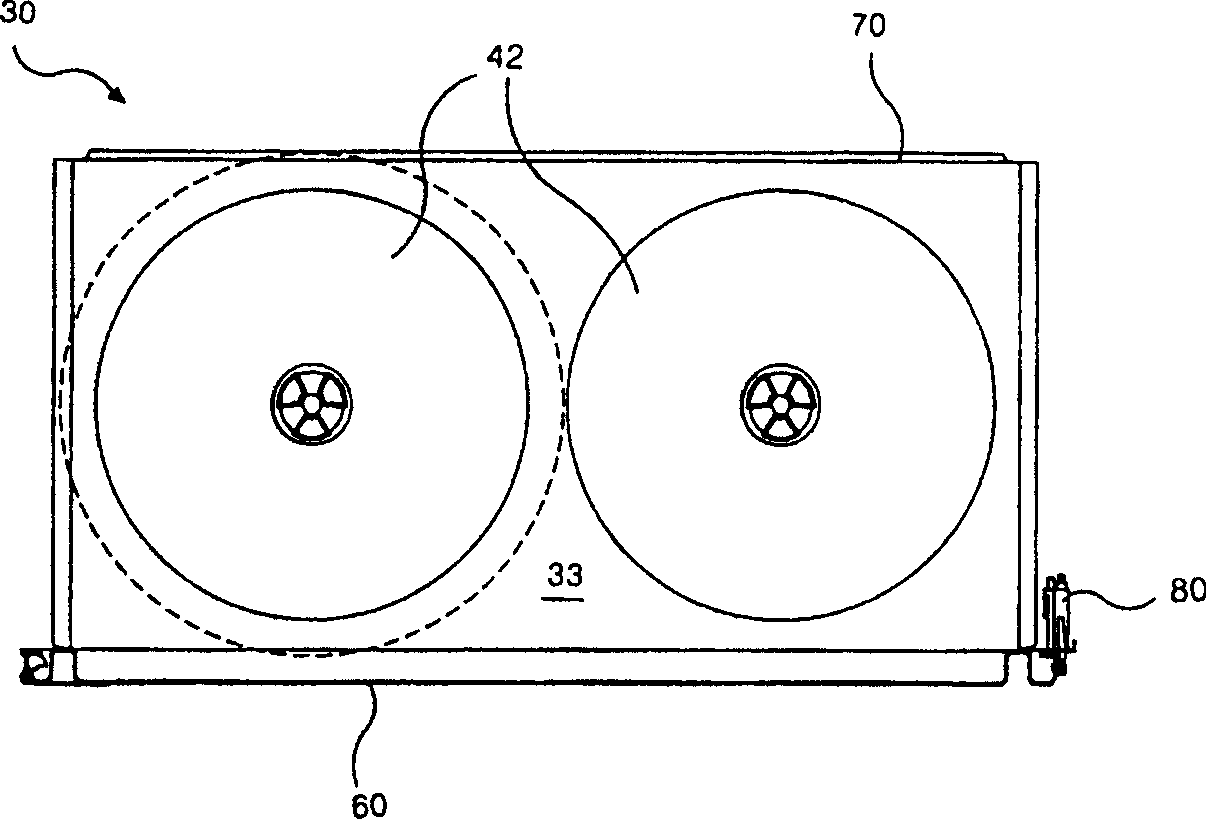
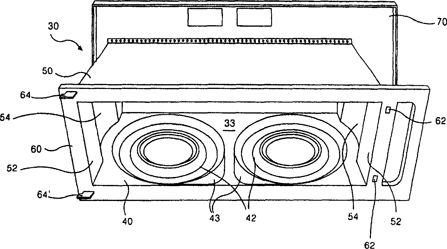
[0033] The cavity structure of the microwave oven of the present invention will be further described in detail in conjunction with the accompanying drawings and specific embodiments: image 3 Represent the stereogram of the cavity of the microwave oven designed by the present invention, Figure 4 Represent the cavity structure plan view in the embodiment of the present invention, Figure 5 It shows a three-dimensional view of the side structure of the cavity in the embodiment of the present invention.

[0034] As can be seen from the figure, in the embodiment of the present invention, the cavity 30 is composed of a lower panel 40 , an upper panel 50 , a front panel 60 and a back panel 70 , and a cooking chamber 33 is formed inside it.

[0035] Firstly, the lower panel 40 forms the bottom of the cavity 30 . On such a lower panel 40, a tray bracket 42 is formed, and the tray bracket 42 forms a circle in order to rotate the tray when food is placed on the tray (not shown). Mor...


PUM


Abstract

The present invention relates to a cavity body structure of microwave oven, and is characterized by that on the side walls formed into two sides walls of the cavity body of said invented microwave oven the stampled structure is formed respectively, and said stamped structure possesses the side surface structure with curvature which can be formed into defined gap with the periphery of material tray support frame formed on the bottom surface of cooking chamber, so that the food placed on the material tray for making treatment does not produce interference with side wall of the cooking chamber, and can more effectively use internal space of cooking chamber, and can maximally widen exterior of cooking chamber, i.e. cavity body space.

Description

technical field [0001] The invention relates to the field of microwave ovens. Background technique [0002] figure 1 and figure 2 Represents the cavity structure of a microwave oven designed in conventional technology. As can be seen from the figure, a cooking chamber 33 is formed inside the cavity 30 . The cooking chamber 33 is a space where the microwave oven performs cooking. [0003] Such a cooking chamber 33 is composed of the following structures. That is, there are lower panels 40 on the bottom and both sides of the cooking chamber 33 . At this time, the portion forming the bottom surface of the cooking chamber 33 and the portions forming the side surfaces are connected at right angles. Furthermore, on the lower panel 40, at the upper ends of the side surfaces of the cooking chamber 33, laps (not shown) of a predetermined width are respectively bent outward at right angles. [0004] The upper panel 7 is installed on the lower panel 40 where the edge is placed....

Claims


Application Information

Patent Timeline
Patent Type & Authority Patents(China)
IPC IPC(8): F24C7/02F24C15/18
Inventor 金寿换
Owner LG ELECTRONICS (TIANJIN) APPLIANCES CO LTD
Why Eureka
Try Eureka