Secondary battery

A technology of secondary battery and collector plate, applied in the direction of secondary battery, secondary battery manufacturing, battery pack components, etc., to achieve the effect of high current collection performance

Inactive Publication Date: 2006-07-19
SANYO ELECTRIC CO LTD
View PDF0 Cites 0 Cited by
  • Summary
  • Abstract
  • Description
  • Claims
  • Application Information

AI Technical Summary

Problems solved by technology

[0012] However, if Image 6 As shown, an arc-shaped convex portion (52) protruding toward the wound electrode body (4) is formed on the current collector plate (50), and at the same time, a through hole (not shown) for forming a cut and raised piece (53) is opened. Since a non-contact area is partially formed between the surface of the collector plate (50) and the bottom surface of the bottomed cylinder (15), when the aforementioned laser welding is performed on the non-contact area, the bottomed cylinder will Body (15) may produce pores after melting

Method used


Image

  • Secondary battery
  • Secondary battery
  • Secondary battery

Examples


Embodiment Construction

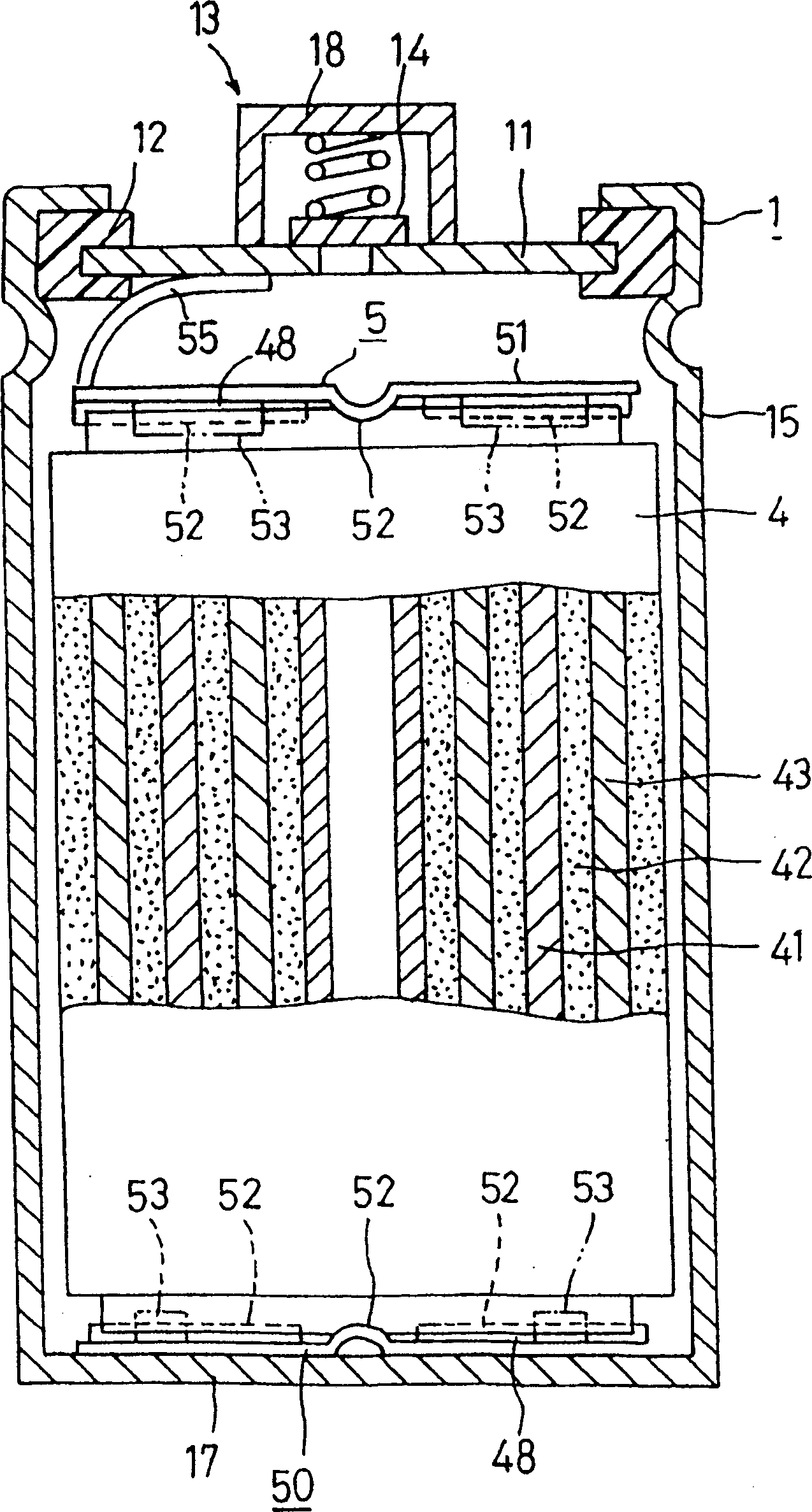
[0034] Hereinafter, embodiments of the present invention will be specifically described with reference to the drawings. Such as figure 1 As shown, the secondary battery of the present invention is constituted by installing a wound electrode body (4) inside a cylindrical battery can (1) whose surface is nickel-plated on a steel base material. The battery can (1) utilizes an insulating member (12) to fix the lid (11) on the opening of the bottomed cylinder (15), forming an outer diameter of 30 mm and a length of 65 mm. A positive terminal (18) incorporating a safety valve (14) is attached to the lid (11) of the battery can (1), and the positive terminal (18) constitutes a positive terminal portion (13). In addition, the negative electrode terminal portion (17) is constituted by the bottom of the bottomed cylindrical body (15).

[0035] Such as Image 6 As shown, the wound electrode body (4) is formed by interposing a belt-shaped separator (42) between each belt-shaped positi...


PUM


Abstract

A secondary cell comprises an electrode unit housed in a cell can comprising a cylinder having a bottom and a closed opening, and a current collector plate 50 is provided at one end of the electrode unit. The current collector plate 50 has a plurality of protrusions 52 extending radially thereof and joined to an edge of the electrode unit. The surface of the current collector plate 50 to be joined to the bottom wall of the cylinder has a flat region R extending on a predetermined closed-loop track on the surface, and the portions of the current collector plate 50 and the cylinder to be joined are subjected along the flat region R to laser welding from outside the cylinder. Accordingly, the cell achieves high current collection efficiency. In fabricating the cell, there is no likelihood that holes will be formed in the cylinder when the current collector plate is welded to the bottom wall of the cylinder.

Description

technical field [0001] The present invention relates to a secondary battery capable of transmitting electric power generated by an electrode body housed in a cylindrical battery can to the outside through a collector plate. Background technique [0002] Secondary battery (battery) configuration such as Figure 11 As shown, the wound electrode body (2) is installed inside the battery can (1). The battery can (1) uses insulating parts (12) to fix the cover (11) on the opening of the bottomed cylinder (15), and the positive terminal with a built-in safety valve (14) is installed on the cover (11) (18). The positive terminal part (13) is formed by the positive terminal (18). In addition, a negative terminal portion (17) is formed by the bottom of the bottomed cylindrical body (15). [0003] The wound electrode body (2) is composed of a strip-shaped positive electrode (21), a separator (22) and a negative electrode (23). The positive electrode (21) and the negative electrode (...

Claims


Application Information

Patent Timeline
Patent Type & Authority Patents(China)
IPC IPC(8): H01M2/26H01M10/04H01M10/40H01M10/05H01M10/0587H01M50/533H01M50/538
CPCH01M10/0587H01M2/263H01M10/0422Y02E60/12Y02E60/10H01M50/538Y02P70/50H01M50/533H01M10/0431H01M10/0525
Inventor 秋田宏之佐藤广一能间俊之米津育郎
Owner SANYO ELECTRIC CO LTD
Why Eureka
Try Eureka