power storage device

An electric storage device and electrode technology, applied in the direction of batteries, circuits, electrical components, etc., can solve problems such as output reduction, and achieve the effects of increasing output, improving power collection effect, and improving power collection efficiency

Active Publication Date: 2017-02-22
TOYOTA IND CORP
View PDF7 Cites 0 Cited by
  • Summary
  • Abstract
  • Description
  • Claims
  • Application Information

AI Technical Summary

Problems solved by technology

However, in a secondary battery, when electric power is taken out from each electrode through a terminal, the resistance of the metal foil that becomes the path of the electric power becomes an important factor that reduces the output.

Method used


Image

  • power storage device
  • power storage device
  • power storage device

Examples


Embodiment Construction

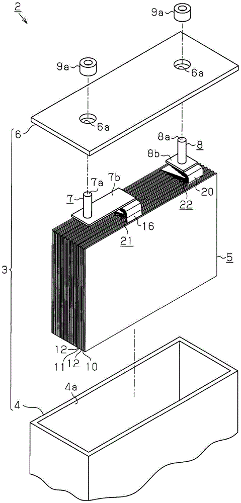
[0029] Below, according to Figure 1 to Figure 7 One embodiment that actualizes the present invention will be described.

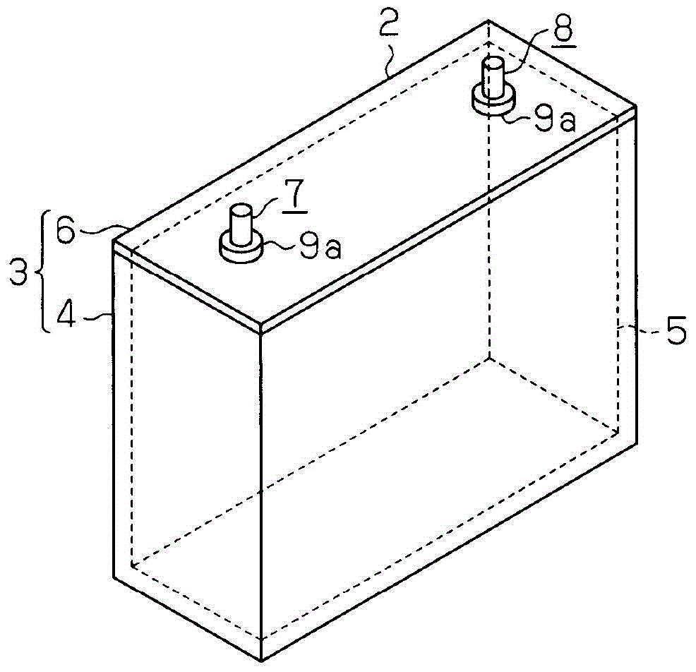
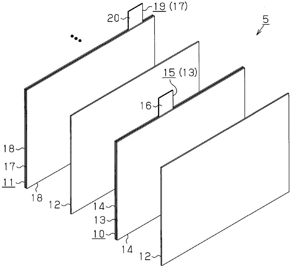
[0030] A secondary battery 2 as a power storage device such as figure 1 as well as figure 2 As shown, an electrode assembly 5 housed in a metal electrolytic tank can 3 is provided. The electrolytic tank 3 includes a rectangular parallelepiped body member 4 and a rectangular plate-shaped lid member 6 that closes the opening 4 a of the body member 4 . Both the main body member 4 and the cover member 6 are made of metal (for example, stainless steel, aluminum). In addition, the secondary battery 2 of the present embodiment is a rectangular battery having a rectangular outer shape. In addition, the secondary battery 2 of this embodiment is a lithium ion battery.

[0031] A positive electrode terminal 7 and a negative electrode terminal 8 for transmitting and receiving electric power to and from the electrode assembly 5 are electrically connected to the e...


PUM


Abstract

When the electrode assembly (5) of the electrical storage device (2) is viewed from the front along the stacking direction, the positive electrode current collector (16) is relative to the virtual reference line (F1) passing through the center of the electrode assembly (5). The distance (X1) of the negative electrode current collecting part (20) relative to the virtual reference line (F1) is different from the distance (Y1). The distance (X1) is between the first imaginary central line (F2) passing through the center of the positive electrode current collecting portion (16) in the width direction (W2) of the positive electrode current collecting portion (16) and the imaginary reference line (F1). distance. The distance (Y1) is between the second imaginary central line (F3) passing through the center of the negative electrode current collecting portion (20) in the width direction (W3) of the negative electrode current collecting portion (20) and the imaginary reference line (F1). distance. Therefore, the electrode assembly (5) has an asymmetric structure.

Description

technical field [0001] The present invention relates to an electrical storage device. Background technique [0002] In vehicles such as EV (Electric Vehicle) and PHV (Plug in Hybrid Vehicle), secondary batteries such as lithium-ion batteries are mounted as power storage devices that store electric power supplied to an electric motor serving as a prime mover. Such secondary batteries are disclosed in Patent Documents 1 and 2, for example. The secondary battery has a negative electrode obtained by coating a negative active material on a metal foil and a positive electrode obtained by coating a positive active material on a metal foil. An electrode assembly with a multilayer structure in which separators made of films are stacked in an insulated manner. [0003] Patent Document 1: Japanese Patent Application Laid-Open No. 7-226232 [0004] Patent Document 2: Japanese Patent Application Laid-Open No. 7-302616 [0005] In the secondary battery, by connecting the terminals to ...

Claims


Application Information

Patent Timeline
Patent Type & Authority Patents(China)
IPC IPC(8): H01M2/26H01M2/30H01M50/528H01M50/533H01M50/54H01M50/55H01M50/566
CPCH01M10/0525H01M50/54H01M50/533H01M50/566H01M50/55H01M2220/20Y02E60/10H01M50/528Y02P70/50
Inventor 南形厚志
Owner TOYOTA IND CORP
Why Eureka
Try Eureka