

Castor type roller controlled by motor
A technology of small casters and rollers, applied in casters, electric steering mechanisms, wheels, etc., can solve problems such as complex structures
- Summary
- Abstract
- Description
- Claims
- Application Information
AI Technical Summary
Problems solved by technology
Method used
Image

Examples
Embodiment Construction
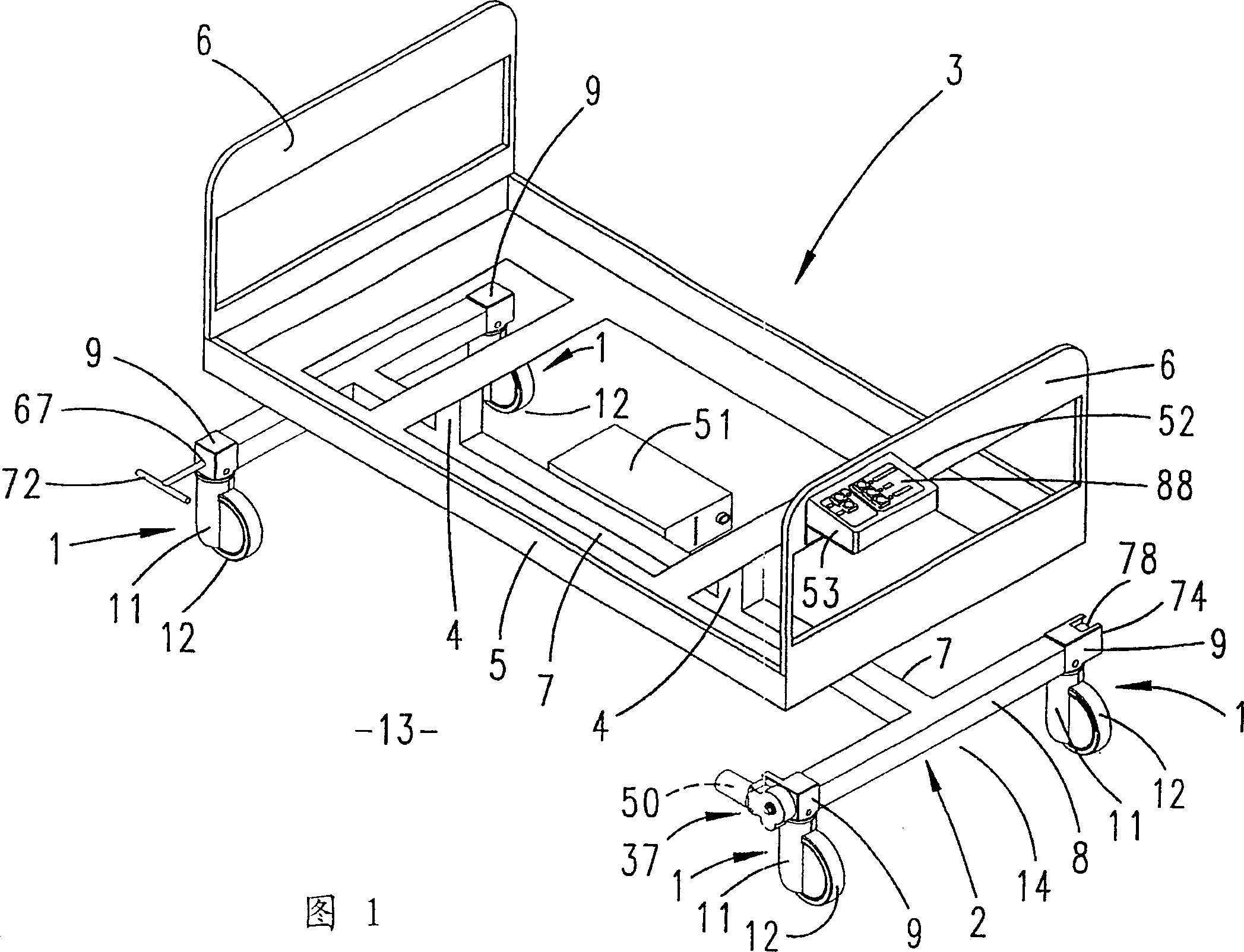
[0024] The rollers 1 according to the invention are made in the form of castors and mounted on the four corners of the mobile mechanism. In the case of the described embodiment, this movement mechanism is the underframe 2 of the hospital bed 3 .
[0025] The underframe 2 is connected to the bed frame 5 by the uprights 4 . The head and feet of the bed frame are vertical boards 6 .
[0026] The bed frame 5 can be separated so that the parts of the frame can be adjusted and fixed to each other to form a bed of a specific profile (not shown in these profile drawings).
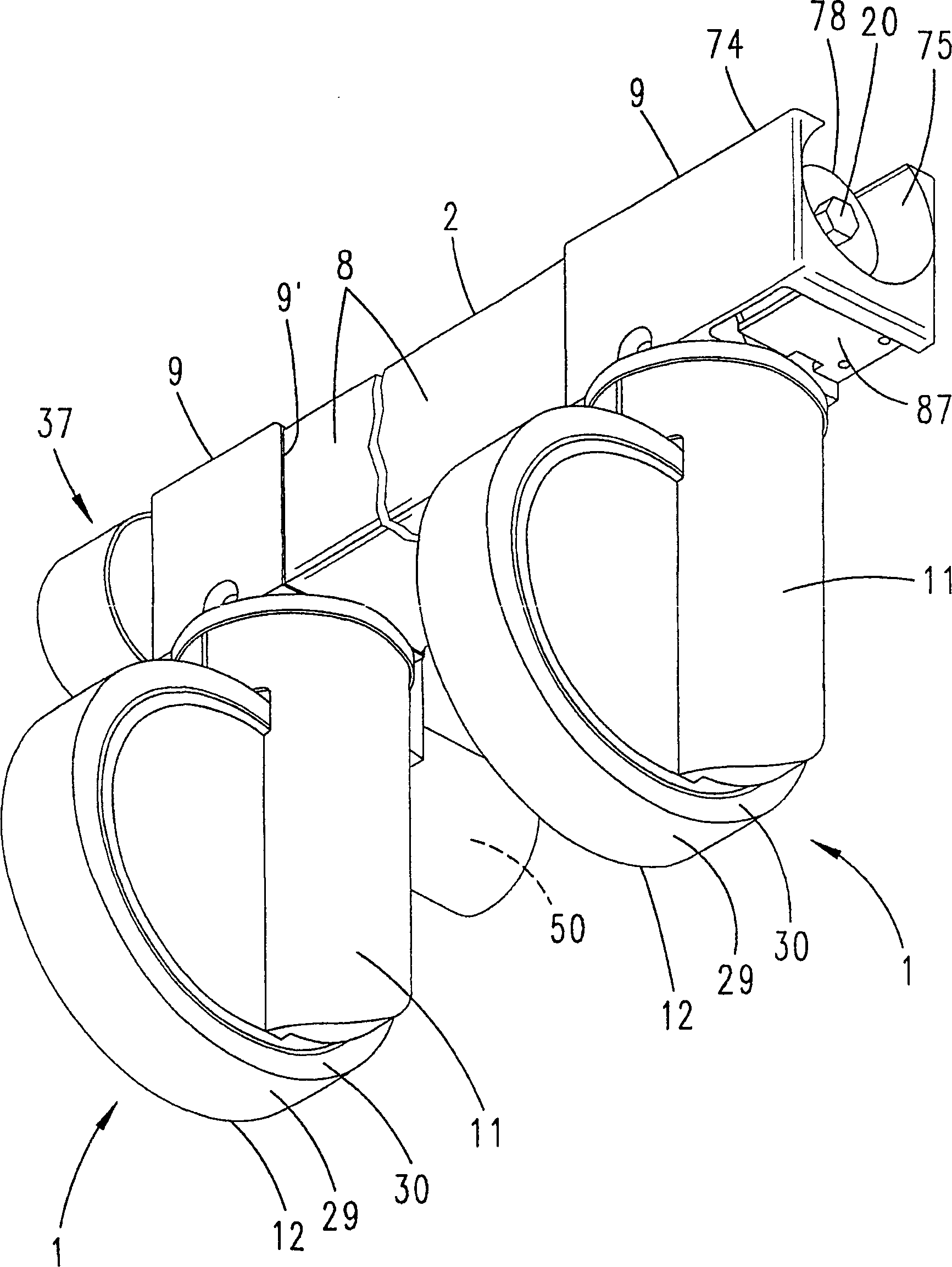
[0027] The chassis 2 is assembled from box parts. The box part comprises a beam 7 as a T-bar; and an arm 8 intersecting the beam 7 at the front end of the bed head. The beam 7 and the arm 8 form two T-shaped intersections.
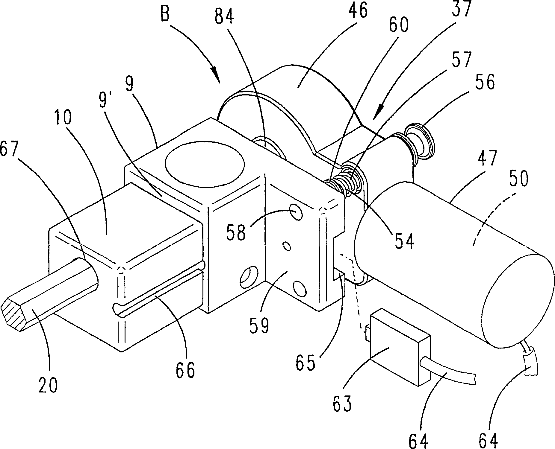
[0028] The roller 1 is mounted on the free end of the arm 8 by means of a support 9 which can be inserted horizontally. The plug-in connection can be made upside down and secured with a cr...
PUM
 Abstract
Description
Claims
Application Information