
Impedance-tuned connector

A connector and connector assembly technology, which is applied in the direction of connection, fixed connection, two-part connection device, etc., can solve problems such as impedance change

Inactive Publication Date: 2006-08-02
MOLEX INC +2
View PDF3 Cites 4 Cited by
  • Summary
  • Abstract
  • Description
  • Claims
  • Application Information

AI Technical Summary

Problems solved by technology

Although it is relatively easy to maintain the desired impedance in an electrical transmission line such as a cable by maintaining a specific geometry or physical configuration of the signal conductors and ground shield, in the area where the connector that incorporates the cable meets the printed circuit board encounter impedance changes

Method used


Image

  • Impedance-tuned connector
  • Impedance-tuned connector
  • Impedance-tuned connector

Examples


Embodiment Construction

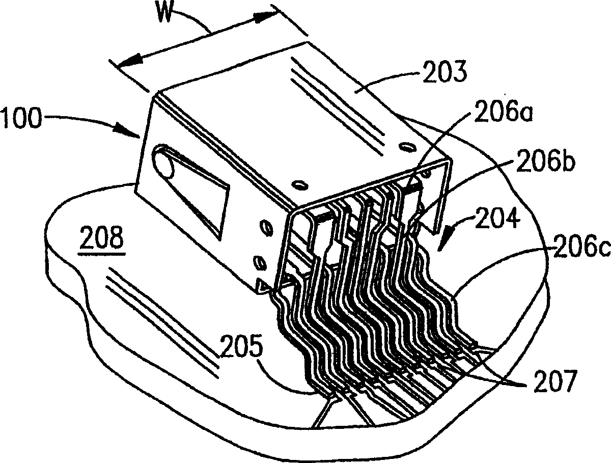
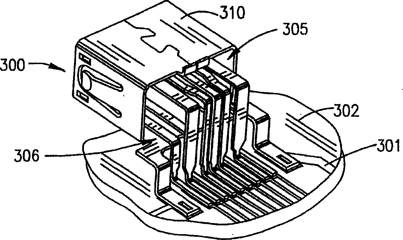
[0042] The present invention proposes improved connectors that are particularly useful in enhancing the performance of high-speed cables, particularly in input-output ("I / O") applications as well as other types of applications, and the present invention seeks to provide Measures of mechanical and electrical consistency are applied to facilitate improved performance of the connector alone and in combination with opposing connectors.

[0043] Many peripheral devices associated with electronic devices such as video cameras or camcorders transmit digital and other signals on different frequencies. Other devices related to the computer, such as the CPU part of the computer, operate at high speed for data transmission. High-speed cables are used to connect these devices to the CPU, and can also be used to connect two or more CPUs together in some applications. A particular cable can be adequately configured to carry these high speed signals, and will usually include differential si...


PUM


Abstract

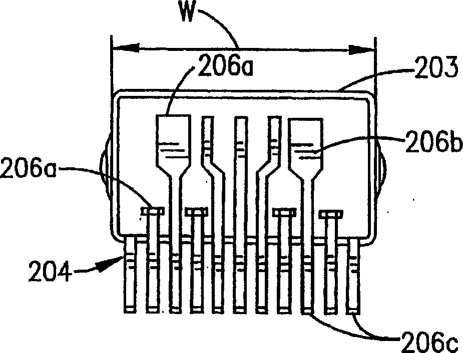
A connector with controlled impedance includes at least one set of differential signal terminals with an associated ground terminal. The ground terminal has a symmetric configuration, while the two differential signal terminals have asymmetric configurations. The asymmetric configurations permit capacitive coupling to occur primarily between the two differential signals in an area of the connector where the inductance of the connector would be high. The two differential signal terminals flank the ground terminal.

Description

technical field [0001] This invention relates generally to connectors, and more particularly to connectors having improved impedance characteristics and for use in connecting signal cables to printed circuit boards. Background technique [0002] Many electronic devices rely on transmission lines for transmitting signals between associated devices of a computer or between peripheral devices and circuit boards. These transmission lines consist of signal cables that enable high-speed data transmission. [0003] These signal cables may use what is known as one or more twisted pairs twisted together along the length of the cable, each twisted pair surrounded by an associated ground shield. These twisted pairs typically receive complementary signal voltages, ie, one wire in the pair sees a +1.0 volt signal and the other wire in the pair sees a -1.0 volt signal. As such, these wires may be referred to as "differential" pairs, a term that refers to the pairs that carry differentia...

Claims


Application Information

Patent Timeline
Patent Type & Authority Patents(China)
IPC IPC(8): H01R13/658H01R12/50H01R12/57H01R13/405H01R13/504H01R13/6471H01R13/6473H01R13/6474
CPCH01R13/6474H01R13/6471H01R23/7073H01R13/405H01R13/504H01R23/6873H01R12/57H01R13/6473H01R12/724H01R13/658
Inventor 戴维L·布伦克尔柯克B·佩洛扎
Owner MOLEX INC
Learn More