Eureka AIR delivers breakthrough ideas for toughest innovation challenges, trusted by R&D personnel around the world.

Linear cutting discharging processing device and its control method

A control method and electric discharge machining technology, applied in electric machining equipment, program control, general control system, etc., can solve the problems of wire electrode breakage and disadvantage

Inactive Publication Date: 2006-08-09
MITSUBISHI ELECTRIC CORP
View PDF1 Cites 0 Cited by
  • Summary
  • Abstract
  • Description
  • Claims
  • Application Information

AI Technical Summary

Problems solved by technology

[0010] In addition, it is easy to cause the wire electrode to break frequently when performing wire-cut EDM at high speed. At this time, the discharge frequency is a very high frequency such as hundreds of KHZ. operation of the arithmetic operation device is unfavorable

Method used


Image

  • Linear cutting discharging processing device and its control method
  • Linear cutting discharging processing device and its control method
  • Linear cutting discharging processing device and its control method

Examples


Embodiment Construction

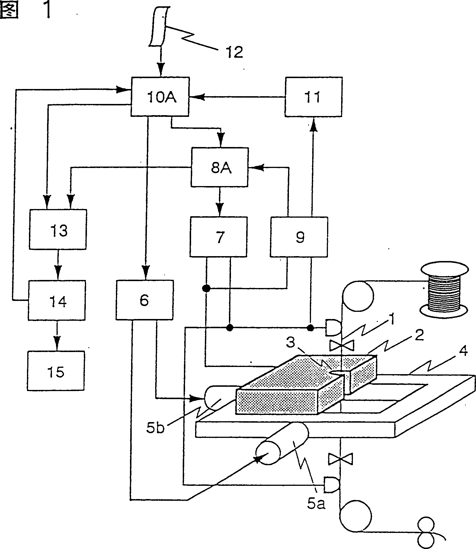
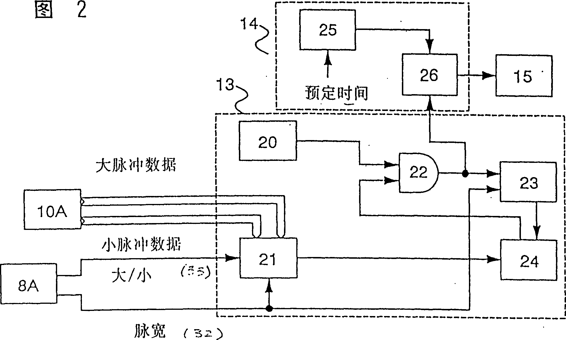
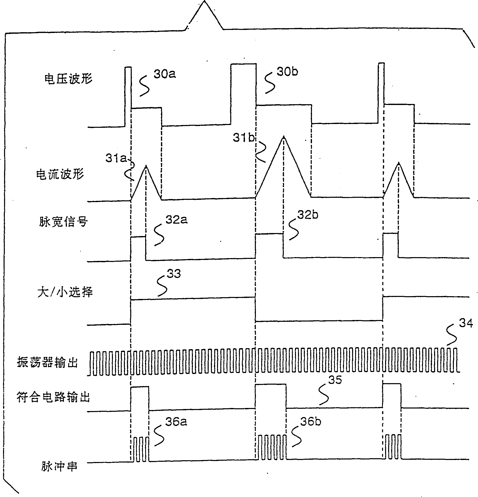
[0051] Referring to Figure 1 to Figure 5 A first embodiment of the present invention is described.

[0052] FIG. 1 depicts a wire-cut electric discharge machining device of the first embodiment. In the figure, 1 represents a linear electrode; 2 represents a workpiece; 3 represents the processing gap formed by the linear electrode 1 and the workpiece 2; 4 represents a worktable for fixing the workpiece 2; 5a represents a drive table 4 along the X-axis direction 5b represents a Y-axis drive motor that drives the workbench 4 along the Y-axis direction; 6 represents a shaft drive control device that controls the X-axis and Y-axis drive motors 5a, 5b; 7 represents that the machining gap 3 provides The processing power supply of the discharge current pulse; 8A represents a processing power supply control circuit that controls the switching operation of the processing power supply 7; 9 represents the voltage detection circuit of the processing voltage detected at the processing gap...


PUM

PropertyMeasurementUnit
diameteraaaaaaaaaa

Abstract

A linear cutting discharging processing device and its control method. The discharging processing device includes a pulse train generate device, a pulse counting device and a control device. The control method includes: outputting a pulse train corresponding to a machining current supplying time range, integrating a pulse number of the pulse train within the specified time, and controlling the machining conditions on the basis of the pulse number integrated result. The present invention can accurately measure the current pulse number provided to machining time without detecting delay, thereby detects the fault machining such as the disconnection of a wire electrode and the generation of an electric arc.

Description

[0001] This application is a divisional application of the patent application with the filing date of September 20, 1995, the application number of 95115769.8, and the title of "Wire Cutting EDM Device and Its Control Method". technical field [0002] The present invention relates to an electrical discharge machining device and a control method thereof, in particular to an electrical discharge machining capable of preventing wire-shaped electrodes from breaking during machining, improving machining efficiency, and preventing abnormal machining operations (such as occurrence of arc discharge) under abnormal conditions Device and control method thereof. Background technique [0003] Figure 22 What is described is a common wire electric discharge machining device. In the figure, 1 represents the linear electrode, 2 represents the workpiece, 3 represents the processing gap formed by the linear electrode 1 and the workpiece 4, 4 represents the worktable for fixing the workpiece ...

Claims


Application Information

Patent Timeline
Patent Type & Authority Patents(China)
IPC IPC(8): B23H1/02B23H7/02B23H7/04
CPCB23H7/04B23H7/16G05B2219/45043
Inventor 佐藤清侍山田久真柄卓司今井祥人佐藤达志
Owner MITSUBISHI ELECTRIC CORP
Why Eureka
Eureka Blog
Learn More