
Microwave oven

A technology of microwave ovens and filter circuits, which is applied in the field of microwave ovens and can solve problems such as noise generation

Inactive Publication Date: 2006-08-30
SAMSUNG ELECTRONICS CO LTD
View PDF0 Cites 0 Cited by
  • Summary
  • Abstract
  • Description
  • Claims
  • Application Information

AI Technical Summary

Problems solved by technology

[0009] However, when high electric power is induced using a conversion circuit on the secondary side of the high voltage transformer 4, noise is commonly generated

Method used

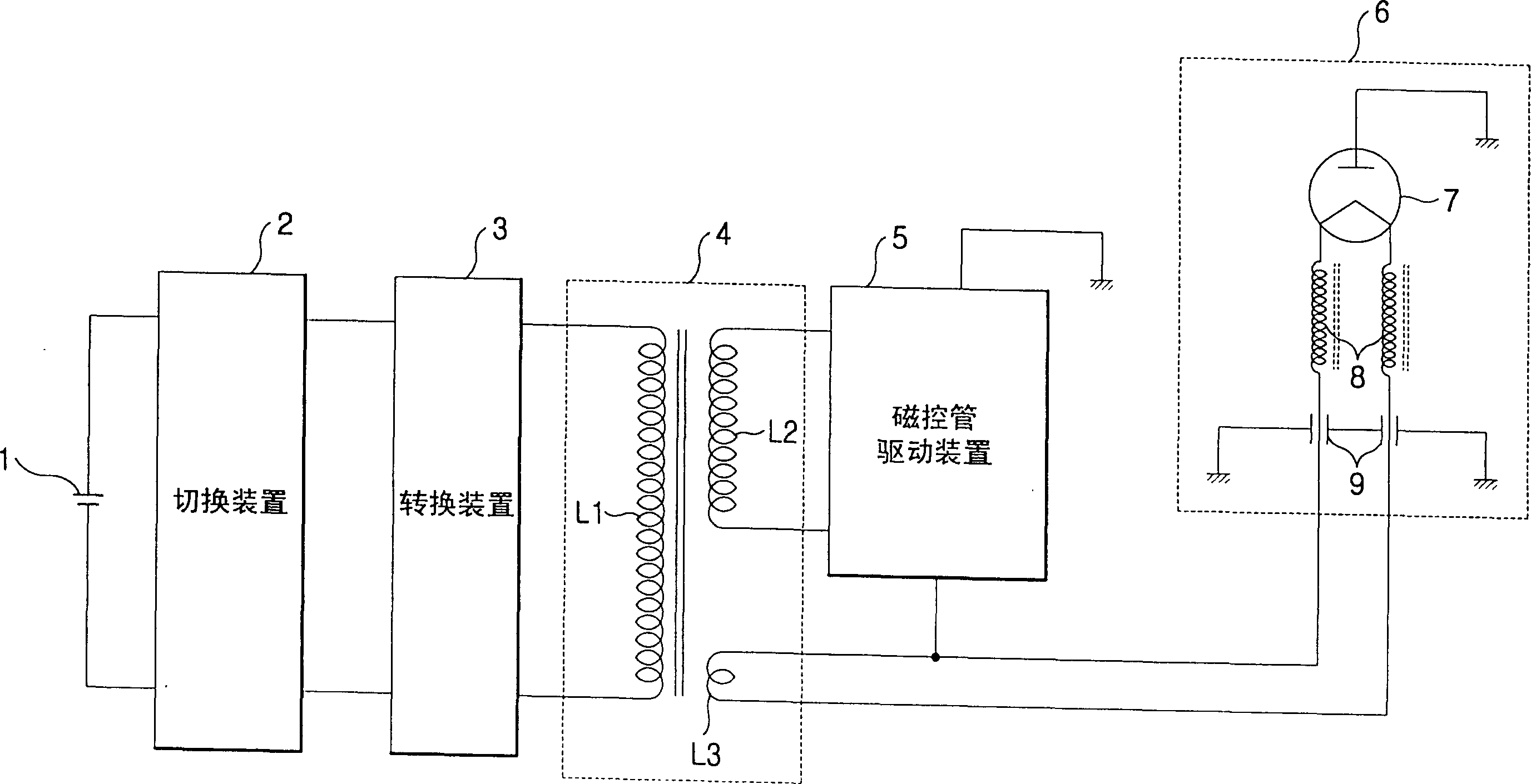
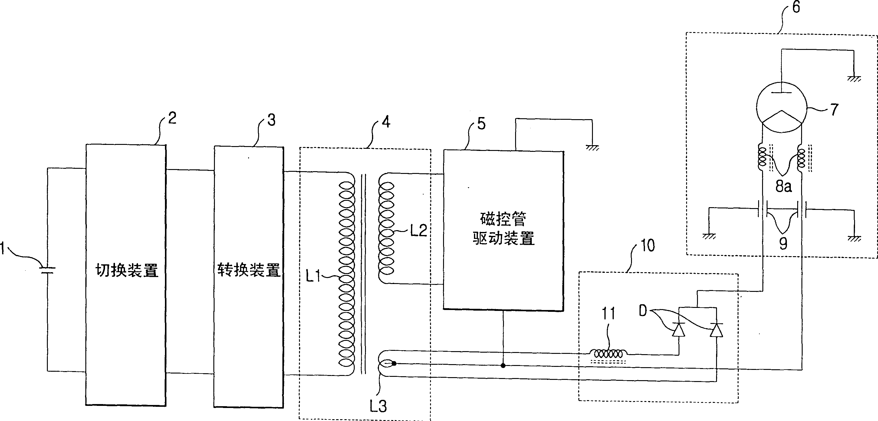
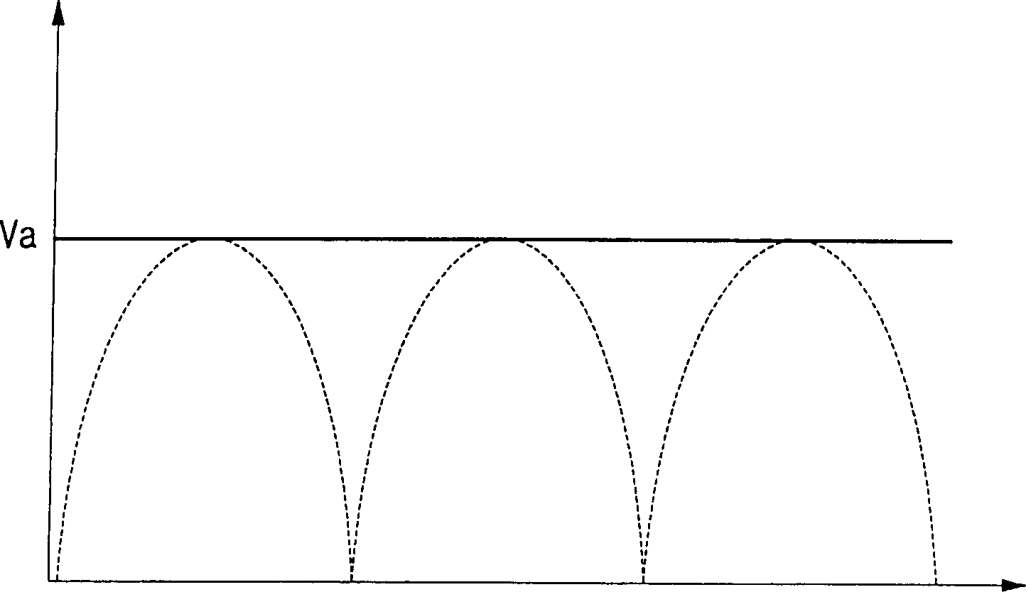

Image

  • Microwave oven
  • Microwave oven
  • Microwave oven

Examples


Embodiment Construction

[0020] Reference will now be made in detail to the preferred embodiment of the invention, examples illustrated in the accompanying drawings, wherein like reference numerals refer to like parts throughout.

[0021] The present invention can be applied to domestic microwave ovens using AC power, and can also be used in microwave ovens using DC power. Furthermore, the present invention can be applied to microwave ovens that select DC and AC power sources. For convenience and unnecessary repetition, the microwave oven to which the present invention is applied using a DC power supply will be described.

[0022] figure 2 Shown is a microwave oven using a DC power supply according to an embodiment of the present invention. The microwave oven includes a DC power supply 1 , a switching device 2 , a converting device 3 , a high-voltage transformer 4 , a magnetron driving device 5 and a magnetron filter box 6 . The microwave oven using DC power also includes a DC power supply device ...


PUM


Abstract

A microwave oven includes a direct current (DC) power supply unit which supplies DC power to a magnetron so as to suppress noise induced in a high voltage line. The DC power supply unit includes at least one rectifying diode and a choke coil. The rectifying diode rectifies high frequency alternating current (AC) power generated by a heater coil into the DC power to suppress noise induced in the high voltage line of a high voltage transformer. The choke coil forms ripples in the DC power and effectively prevents a moding of the magnetron, which is generated where a constant DC voltage is supplied.

Description

technical field [0001] The present invention relates to a microwave oven, and more particularly to a microwave oven capable of suppressing noise induced in a high voltage line due to the use of a converter. Background technique [0002] Generally, microwave ovens operate by converting commercial alternating current (AC) power into high voltage to drive a magnetron for cooking. Since the microwave oven uses a commercial AC power source, it is difficult to install and use the microwave oven in a vehicle such as a car. [0003] Currently, a microwave oven has been developed that can cook food using a direct current (DC) power source, such as a battery. This type of microwave oven uses a conversion circuit to convert the DC voltage into the AC voltage required to drive the magnetron. [0004] figure 1 Shown is a conventional microwave oven using a DC power supply. The conventional microwave oven includes a DC power supply 1, a switching device 2, a conversion device 3, a high...

Claims


Application Information

Patent Timeline
Patent Type & Authority Patents(China)
IPC IPC(8): H05B6/66F24C7/02H05B6/68
CPCH05B6/666H05B6/68
Inventor 张成德韩大成韩龙云姜翰成姜光锡
Owner SAMSUNG ELECTRONICS CO LTD
Learn More