Optical filter, and laser light source and optical transceiver using the same

An optical filter and laser source technology, applied in the field of optical filters, can solve problems such as difficulty in preventing mode hopping

Pending Publication Date: 2020-05-12
DENSO CORP
View PDF7 Cites 0 Cited by
  • Summary
  • Abstract
  • Description
  • Claims
  • Application Information

AI Technical Summary

Problems solved by technology

Preventing mode hopping can be difficult
Even if oscillation occurs at the second highest peak, since the wavelength of the second highest peak is close to the wavelength of the highest peak, this state may not be detected by the control unit etc.

Method used


Image

  • Optical filter, and laser light source and optical transceiver using the same
  • Optical filter, and laser light source and optical transceiver using the same
  • Optical filter, and laser light source and optical transceiver using the same

Examples


no. 1 approach

[0047] refer to Figure 1-8 The first embodiment will be described. In this embodiment mode, a laser light source using an optical filter is described.

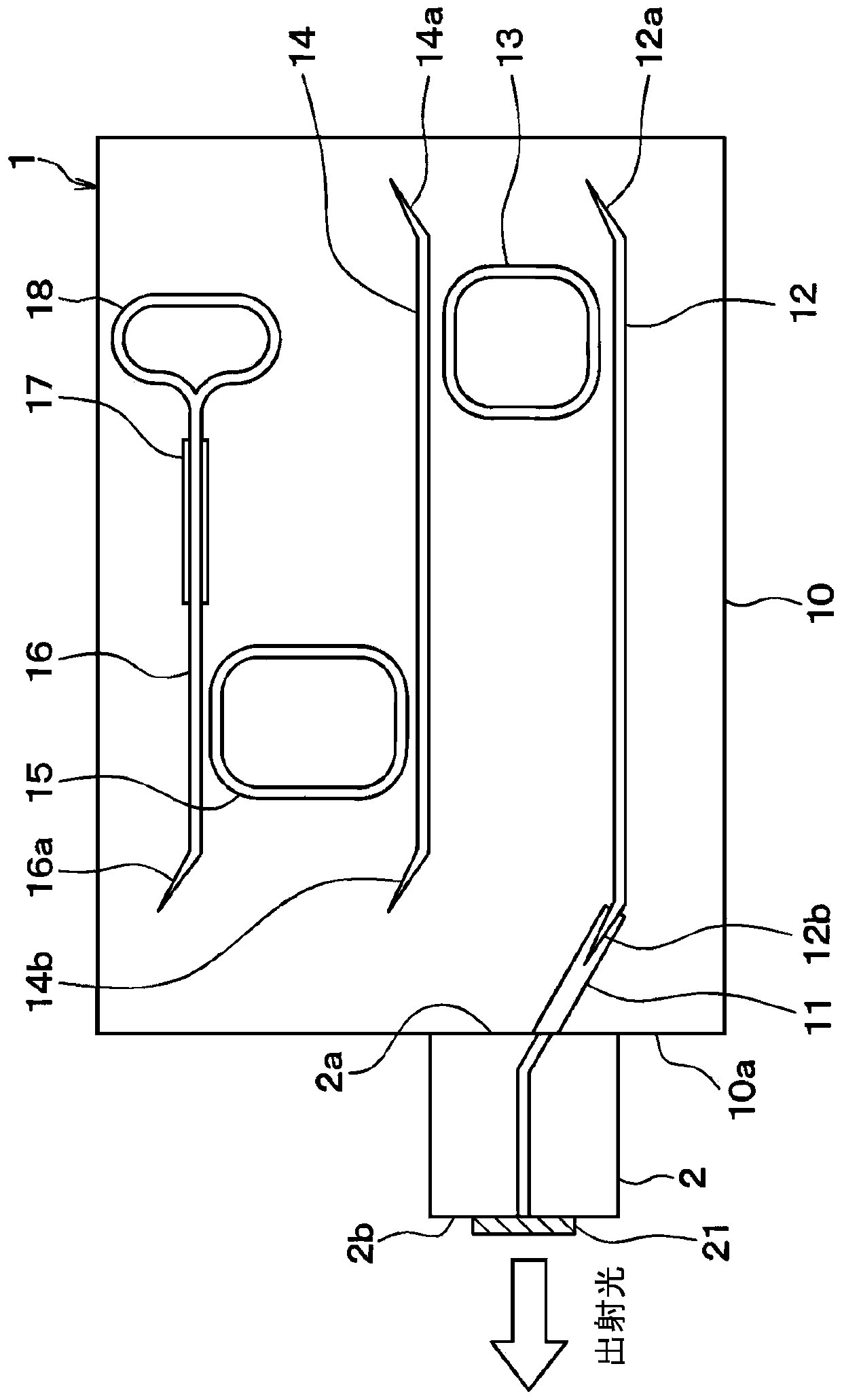
[0048] Such as figure 1As shown, the laser source includes an optical filter 1 and a semiconductor optical amplifier (SOA) 2 . The laser source emits inner outgoing light from SOA2 to filter 1, extracts intense light that has entered a resonance state in optical filter 1 and SOA, and outputs the intense light from SOA2 to the outside as outer outgoing light.

[0049] The optical filter 1 is formed, for example, by performing a semiconductor process using the semiconductor substrate 10 . Specifically, the semiconductor substrate 10 included in the optical filter 1 is equipped with a spot size converter (optical spot size converter, SSC for short) 11, a first waveguide 12, a first ring resonator 13, a second waveguide 14, a second A ring resonator 15, a third waveguide 16, a modulator 17, a ring mirror 18, and the like.

...

no. 2 approach

[0131] The second embodiment is described below. This embodiment differs from the first embodiment in the light extraction direction and the like. Other configurations are similar to those of the first embodiment. Only the parts different from the first embodiment will be described.

[0132] In the first embodiment, when laser oscillation occurs, light is output from the mirror 21 corresponding to the first reflector. In the present embodiment, light is output from a portion different from the mirror 21 .

[0133] In this embodiment, the second reflector is not the annular mirror 18 as in the first embodiment, but as Figure 20 A directional coupler 40 is shown. The directional coupler 40 is folded back from the third waveguide 16 in a meandering manner. In this embodiment, the tip of the directional coupler 40 is directed to the end face 10b of the semiconductor substrate 10, which is opposite to the end face 10a on which the SOA 2 is provided.

[0134] Specifically, th...

no. 3 approach

[0141] A third embodiment is described below. The present embodiment differs from the first and second embodiments in the configuration between the first ring resonator 13 and the second ring resonator 15 . Other configurations are similar to those of the first and second embodiments. Only the parts different from the first and second embodiments are described. In the present embodiment, an example in which light is output through the reflection mirror 21 of the SOA2 as in the first embodiment will be described. Light may be output from a portion different from the reflection mirror 21 as in the second embodiment.

[0142] In the present embodiment, the second waveguide 14 included in the first and second embodiments is omitted. Specifically, as Figure 22 As shown, the first ring resonator 13 and the second ring resonator 15 are adjacent to each other. One side of the first ring resonator 13 and one side of the second ring resonator 15 are opposed to each other with a pr...


PUM

PropertyMeasurementUnit
perimeteraaaaaaaaaa
reflectanceaaaaaaaaaa

Abstract

An optical filter includes a first ring resonator a second ring resonator having different perimeters, and a waveguide optically coupled to the first ring resonator and transmit light to the first ring resonator. Light incident on the waveguide is transmitted to the second ring resonator through the first ring resonator. A free spectral range of a transmission spectrum of the first ring resonatorand a free spectral range of a transmission spectrum of the second ring resonator are staggered to each other, and are set so that a transmission spectrum of a double ring corresponding to a syntheticspectrum of the transmission spectrum of the first ring resonator and the transmission spectrum of the second ring resonator has a highest first peak at an arbitrary wavelength.

Description

[0001] Cross References to Related Applications [0002] This application is based on Japanese Patent Application No. 2018-207488 filed on November 2, 2018, the disclosure of which is incorporated herein by reference. technical field [0003] The present invention relates to a wavelength-variable optical filter using a ring resonator, and a laser source and an optical transceiver using the optical filter. Background technique [0004] A laser source including an optical filter may have a configuration in which outgoing light from a semiconductor optical amplifier (referred to as "SOA") is input to two ring resonators as it travels through a waveguide, followed by Reflected by a ring mirror on the end to return to the SOA. The dimensions of the individual ring resonators are made slightly different from each other so that free spectral ranges (referred to as "FSR") of the transmission spectra of the individual ring resonators obtained when output light is input are slightly ...

Claims


Application Information

Patent Timeline
Patent Type & Authority Applications(China)
IPC IPC(8): H01S5/10
CPCH01S5/10H01S5/1071H01S5/101H01S5/142H01S5/0287H01S3/08059H01S3/08027H04B10/503H04B10/40
Inventor 小田敏宏
Owner DENSO CORP
Why Eureka
Try Eureka