
Suction nozzle of vacuum cleaner

A technology for vacuum cleaners and nozzle heads, which is applied in the direction of suction nozzles, and can solve the problems of impossible suction work and power consumption of suction nozzles

Inactive Publication Date: 2006-11-15
VORWERK & CO INTERHOLDING GMBH
View PDF0 Cites 3 Cited by
  • Summary
  • Abstract
  • Description
  • Claims
  • Application Information

AI Technical Summary

Problems solved by technology

This lateral movement requires more force for the user
When the size of the opening of a niche is significantly smaller than the width of the nozzle, suction is not possible with known nozzles, for which it is sometimes necessary to replace slit nozzles or other similar nozzles

Method used


Image

  • Suction nozzle of vacuum cleaner
  • Suction nozzle of vacuum cleaner
  • Suction nozzle of vacuum cleaner

Examples


Embodiment Construction

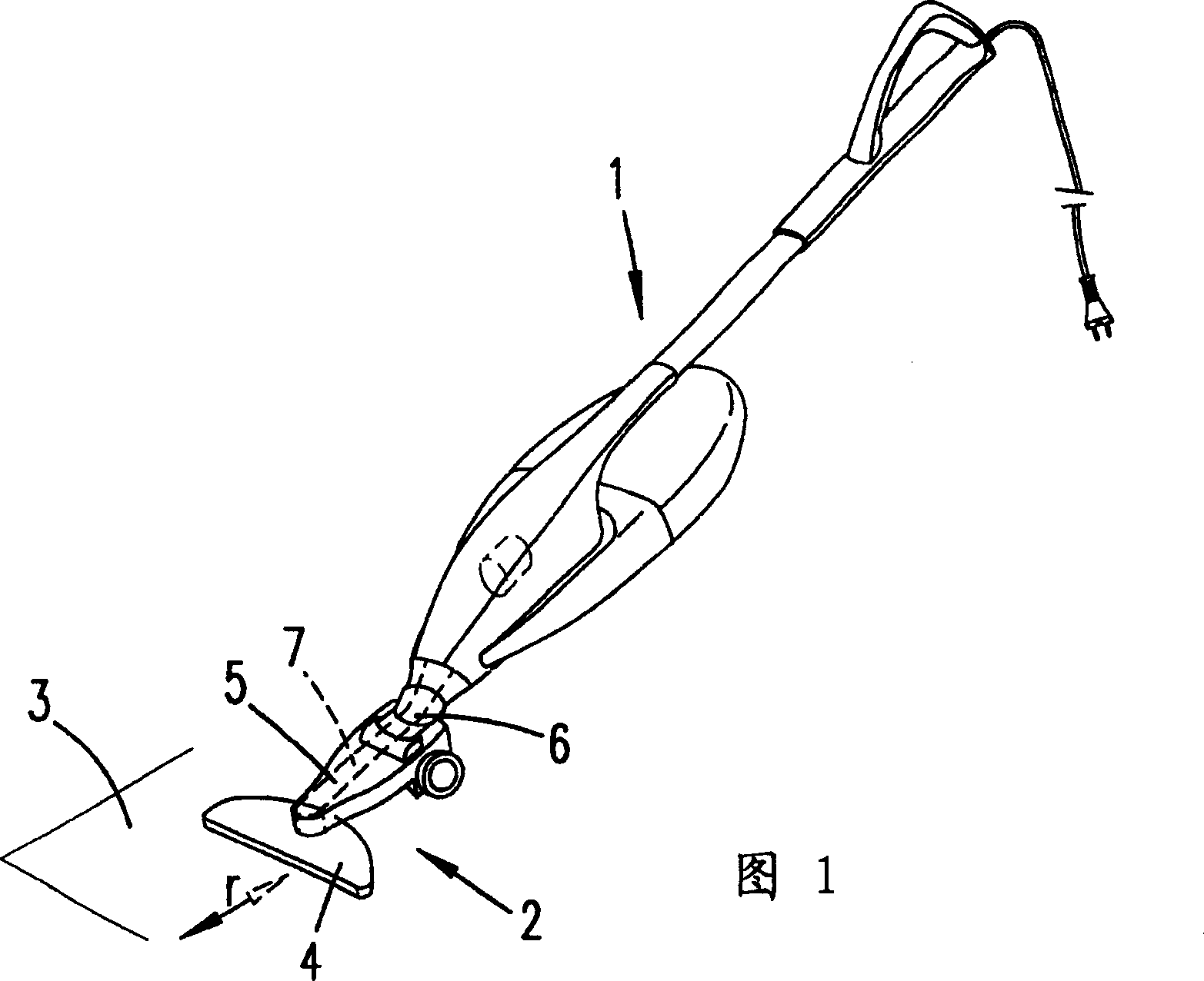
[0039] Firstly, a vacuum cleaner 1 with a suction nozzle 2 for treating a floor 3 is depicted and described with reference to FIG. 1 . In the illustrated embodiment the nozzle 2 is a hard floor nozzle. However, the features of the suction nozzle 2 described below are also conceivable with rotating suction nozzles for cleaning carpets.

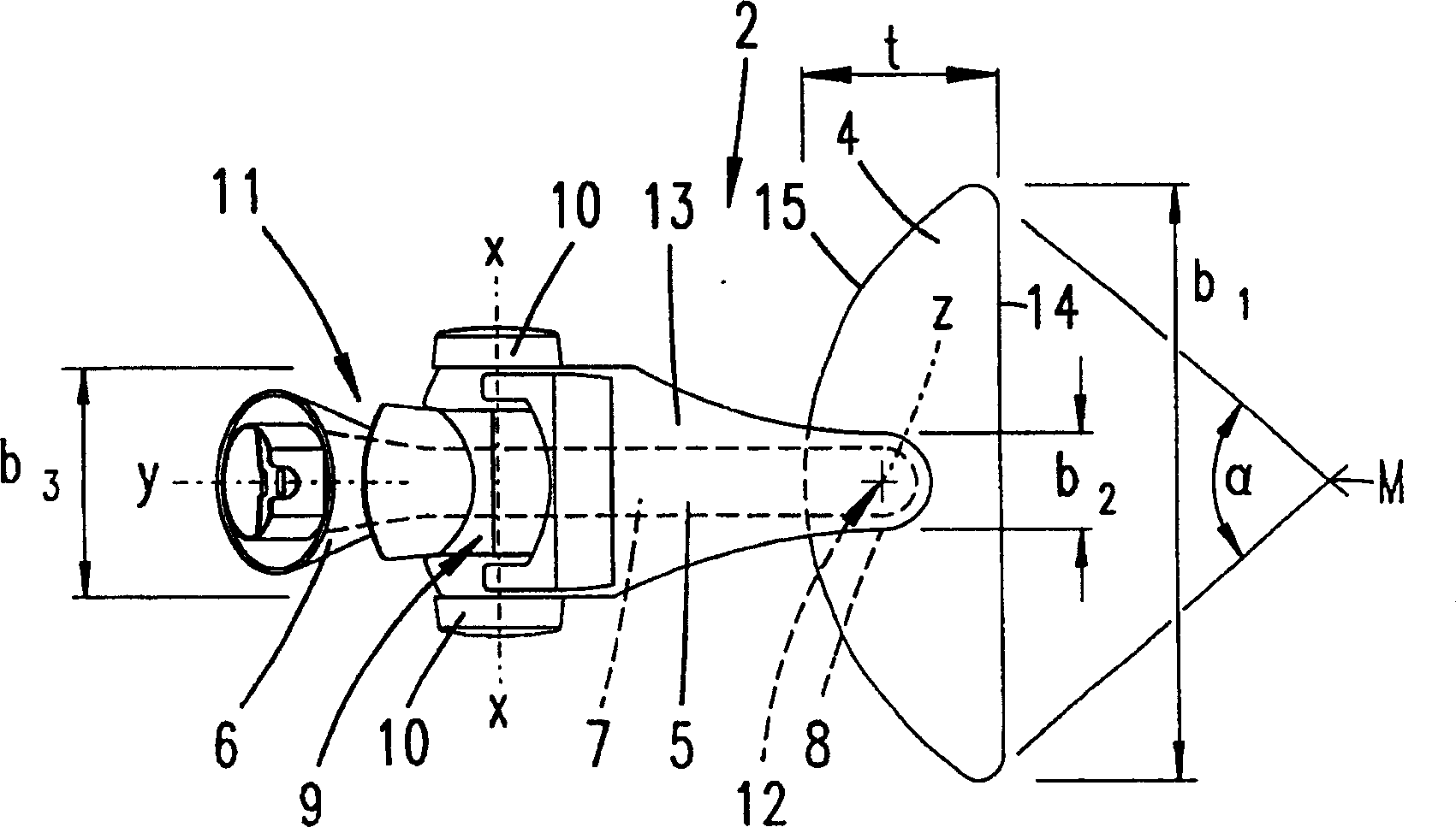
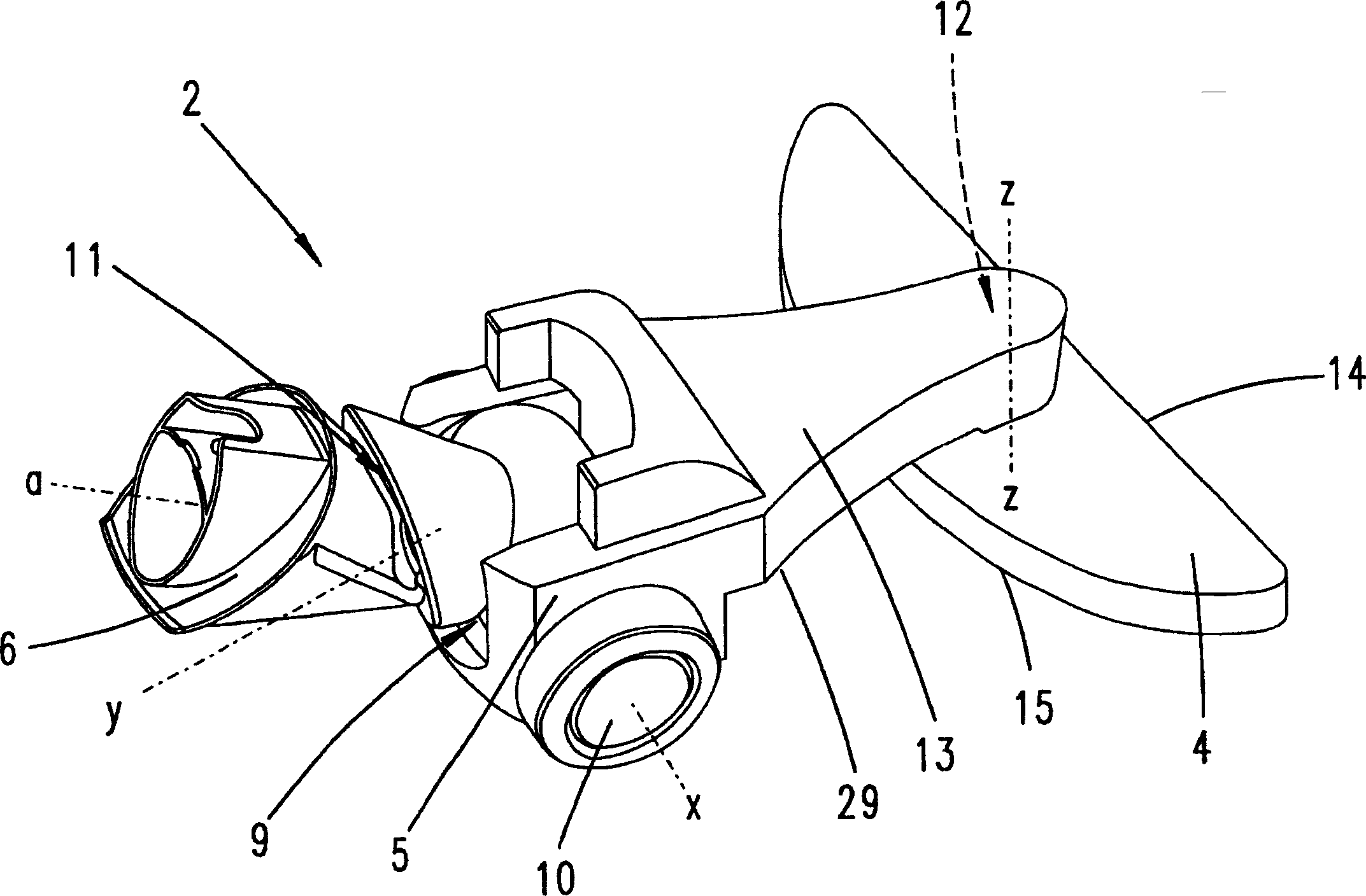
[0040] The suction nozzle 2 basically consists of a nozzle head 4 placed on the ground 3 and a nozzle body 5 connecting the nozzle head 4 with the vacuum cleaner 1, wherein a connecting pipe 6 is constructed on the nozzle body 5 so that the suction The mouth 2 is connected to the vacuum cleaner 1 . From the connecting pipe 6 a suction channel 7 extends through the nozzle body 5 , which opens into the nozzle tip 4 . The suction opening is marked with reference numeral 8 in the figure.

[0041] The connecting pipe 6 is arranged in the upper side of an end region of the nozzle body 5 such that the connecting pipe 6 is pivotable in a first swive...


PUM


Abstract

The nozzle (2) is provided with a suction duct (7), which extending from the connection stub (6) through the nozzle body (5) opens out in the nozzle head (4). The nozzle head is designed swivelable relative to the nozzle body. The swiveling ability is achieved with a joint (12) having a vertical joint axis (Z).

Description

technical field [0001] The invention relates to a suction nozzle for a vacuum cleaner, especially a suction nozzle for hard floors, which has a nozzle head placed on the floor and a nozzle body for connecting the nozzle head to a vacuum cleaner, wherein a connection is formed on the nozzle body Tube and the suction nozzle can move together with the running wheel or through the sliding surface, a suction channel is arranged in the nozzle body, which extends from the connecting pipe through the nozzle body and then leads into the nozzle head. Background technique [0002] Nozzles for vacuum cleaners of the above-mentioned type are known. Correspondingly designed hard-floor suction nozzles are proposed for treating hard floors, and correspondingly designed suction nozzles are provided for treating carpeted floors, preferably with rotating bristle rollers. Suctioning in particular in alcoves, or suctioning around objects such as chair legs or table legs...

Claims


Application Information

Patent Timeline
Patent Type & Authority Patents(China)
IPC IPC(8): A47L9/02
CPCA47L9/02
Inventor 佩特拉·莱曼托马斯·施特罗迈耶托马斯·桑德卡斯坦·雅各布斯伯恩哈德·朔伊伦马库斯·科尼利森乌尔里克·凯克金泰尔·马尔范特
Owner VORWERK & CO INTERHOLDING GMBH
Learn More