Variable orifice flow sensor

A flow sensor, variable technology, applied in the direction of sensor, non-electric variable control, liquid/fluid solid measurement, etc., can solve the problems of hardness or stiffness loss, responsiveness loss, flap stiffness loss, etc., to increase service life, Good resolution, long life effect

Inactive Publication Date: 2001-02-21
BIRD PRODS
View PDF3 Cites 16 Cited by
  • Summary
  • Abstract
  • Description
  • Claims
  • Application Information

AI Technical Summary

Problems solved by technology

However, the annealing treatment softens the stainless steel, and the resulting loss of hardness or stiffness results in a measurable loss of responsivity of the

Method used


Image

  • Variable orifice flow sensor
  • Variable orifice flow sensor
  • Variable orifice flow sensor

Examples


Example Embodiment

[0021] DETAILED DESCRIPTION OF THE PREFERRED EMBODIMENT

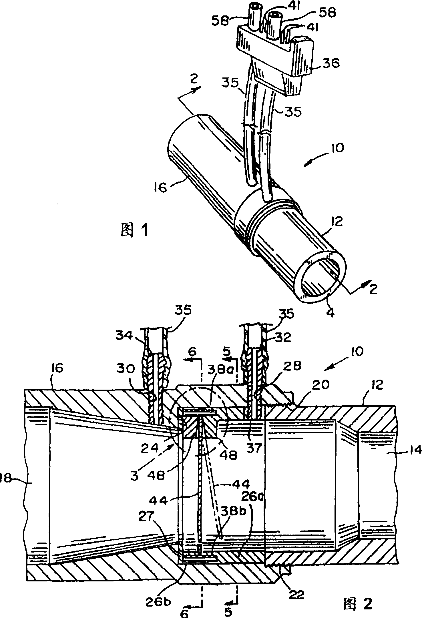
[0022] Referring now to Figures 1 through 8, a variable orifice fluid flow sensor 10 is shown in accordance with a preferred embodiment of the present invention. As best shown in FIGS. 1 and 2 , the sensor 10 includes a first tube 12 defining a first fluid flow orifice 14 and a second tube 16 defining a second fluid flow orifice 18 . The second tubular member 16 has an internally threaded opening 20 opposite the second fluid flow orifice 18 that receives the externally threaded end 22 of the first tubular member 12 . In this way, the first and second pipe members 12, 16 are releasably coupled to each other through the mating threads of the threaded opening 20 and the threaded end 22. Because the sensor 10 is a bidirectional sensor, each fluid flow port 14, 18 can be used as either an input port or an output port.

[0023] An annular shoulder 24 is located inside the second tubular member 16 and extends inwardly from t...


PUM


Abstract

A variable orifice flow sensor (10) includes a flow conduit member defining a flow orifice and fluidly connecting first and second fluid flow ports (12, 16), a flapper of magnetizable sheet metal that is mount in the conduit member by a hinge portion so that the flapper angularly deflects out of the plane of the orifice (18) in response to fluid flow through the conduit member to vary the effective fluid flow cross-sectional area of the orifice in proportion to the flow rate of fluid through the conduit member, and a pressure sensing tap on either side of the flapper. A deflection-limiting surface is provided in the conduit member adjacent the hinge portion. The hinge portion abuts against the deflection-limiting surface when the flapper experiences an angular deflection at least equal to a predefined angle in response to a fluid flow rate that is at least equal to a predetermined value, whereby overstressing the hinge portion is minimized.

Description

Background of the invention [0001] The present invention generally relates to the field of fluid flow sensors. In particular, it relates to improvements in fluid flow sensors of the variable orifice or variable blocking area type, which are commonly used in conjunction with pressure transducers to generate a differential pressure signal from a flow of fluid (especially gas) in a pipe, wherein The value of the differential pressure signal is related to the flow rate value. The volume can be found by integrating the flow rate value against time in turn. [0002] Flow sensors of the kind described above have been commonly used in medical applications, in particular to measure the flow rate of breathing gas in medical respirators. Specific examples of such flow sensors are found in the following US patents: Stupecky 4,989,456; Guillaume et al. 4,993,269; and Stupecky 5,038,621. These patents refer to variable orifice flow sensors using hinged stoppers or flaps that fit within t...

Claims


Application Information

Patent Timeline
IPC IPC(8): A61B5/087A61M5/00G01F1/36G01F1/40G01F1/42
CPCG01F1/363G01F1/40G01F1/42A61B5/0876
Inventor C·I·乔巴努D·谢弗
Owner BIRD PRODS
Why Eureka
Try Eureka