Optical disc and optical disc drive

A technology of optical disc drive and optical disc, which is applied in the direction of instruments, light beam reproduction, optical record carrier, etc., and can solve the problems of increasing manufacturing costs

Inactive Publication Date: 2006-12-20
SONY CORP +3
View PDF0 Cites 0 Cited by
  • Summary
  • Abstract
  • Description
  • Claims
  • Application Information

AI Technical Summary

Problems solved by technology

However, for such an optical disc drive, the disc tilt

Method used


Image

  • Optical disc and optical disc drive
  • Optical disc and optical disc drive
  • Optical disc and optical disc drive

Examples


Embodiment Construction

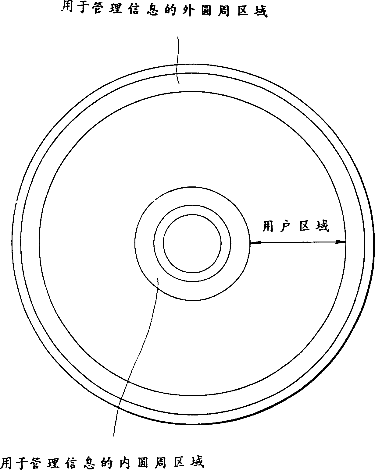
[0047] now refer to figure 2 , to illustrate the magneto-optical disk (hereinafter simply referred to as "disc D") of the present invention. As shown in the figure, the disc D has management information areas formed along the inner and outer peripheries, respectively, for a predetermined number of tracks, respectively. Each of such management information areas includes an area in which disc management information is recorded, a buffer area, a test area, and others. The disc D also forms a user area between the inner and outer circumference management information areas, and the user records data to or plays back data from the user area.

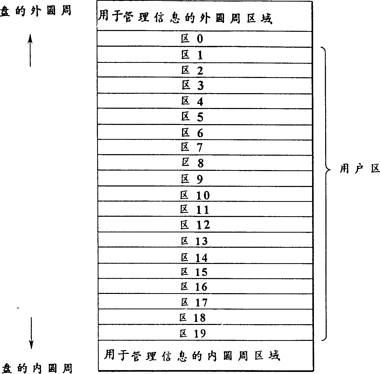
[0048] For example, if image 3 As shown, the user area is divided into 20 areas including 0 to 19. Data is to be recorded to or reproduced from such an optical disc D by the zone CAV or zone CLV method, for example.

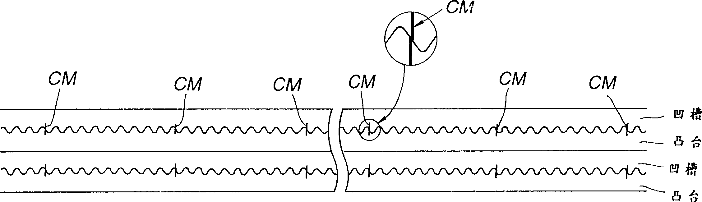
[0049] refer to Figure 4 and 5A to 5C, describe the structure of tracks, frames and segments.

[0050] Figure 4 Show...


PUM


Abstract

An optical disc and an optical disc drive for the optical disc are provided which are suitable for recording data with a high density. The optical disc D uses both lands and grooves as recording tracks. Each of the tracks consists of one address segment and forty five data segments. The address segment is wobbled at one side thereof. Each of the data segments is a DC groove. The address segment records an address information including a sync signal, frame address, track address and CRC, a tilt pattern and a clock mark. The clock mark is adapted to reflect laser beam in one amount before the mark and in another amount after the mark. The tilt pattern has a different track pitch from those in other areas. The data segments record data magneto-optically.

Description

technical field [0001] The present invention relates to an optical disc on which lands and grooves are formed which together form a data recording track and an optical disc drive for the optical disc. Background technique [0002] Well-known data recording media include optical discs such as magneto-optical type, phase-change type, and the like. They include read-only ROM discs, recordable discs, recordable / reproducible RAM discs, so-called partial ROM discs having a ROM area and a RAM area, etc. [0003] In addition, in order to achieve a larger data storage capacity, some so-called land / groove recording type optical discs have been proposed, which are designed to record data on both lands and grooves. [0004] In these general optical discs, recording tracks are wobbled to provide servo control information and address information (ADIP) for data recording and playback. But in ordinary optical discs, due to the amount of light change caused by the wobble and the disturbin...

Claims


Application Information

Patent Timeline
IPC IPC(8): G11B11/105G11B7/00G11B7/005G11B7/007G11B7/09G11B7/095G11B7/24079G11B7/24082G11B7/24097G11B27/19G11B27/30
CPCG11B7/00745G11B7/007G11B7/00718G11B7/0938G11B7/0956G11B11/10515G11B11/10582G11B27/19G11B27/3027G11B2220/20G11B7/013G11B2007/00754G11B2007/00709G11B2007/0133
Inventor 飞田実前田茂己日置敏昭松浦道雄
Owner SONY CORP
Why Eureka
Try Eureka