Air-cooled absorption type refrigerating plant

An absorption refrigeration and air cooling technology, which is applied in adsorption machines, boiler absorbers, absorbents/adsorbents, etc., can solve the problems of ensuring the maintenance space, the difficulty of ensuring the suction space of the air intake port, and the large-scale device body. Achieve the effect of ensuring the heat release area, reducing the air resistance, and reducing the installation area

Inactive Publication Date: 2007-01-10
DAIKIN IND LTD
View PDF6 Cites 0 Cited by
  • Summary
  • Abstract
  • Description
  • Claims
  • Application Information

AI Technical Summary

Problems solved by technology

[0005] However, in the case of the air-cooled absorption refrigerating apparatus of the above-mentioned well-known example, since the air suction port is formed on three sides, the remaining one side has to be used as a maintenance space.
As a result, if a plurality of units are connected to achieve a large amount of refrigeration, it becomes difficult to secure maintenance space and suction space for the air suction port.
[0006] In addition, in order to obtain a large cooling capacity of the refrigeration device, if the method of enlarging the heat dissipation area of ​​the air-cooled absorber and the air-cooled condenser is adopted, there will be a problem of increasing the size of the device body.

Method used


Image

  • Air-cooled absorption type refrigerating plant
  • Air-cooled absorption type refrigerating plant
  • Air-cooled absorption type refrigerating plant

Examples


Embodiment Construction

[0034] Hereinafter, the best embodiment of the invention of the present application will be described with reference to the attached drawings.

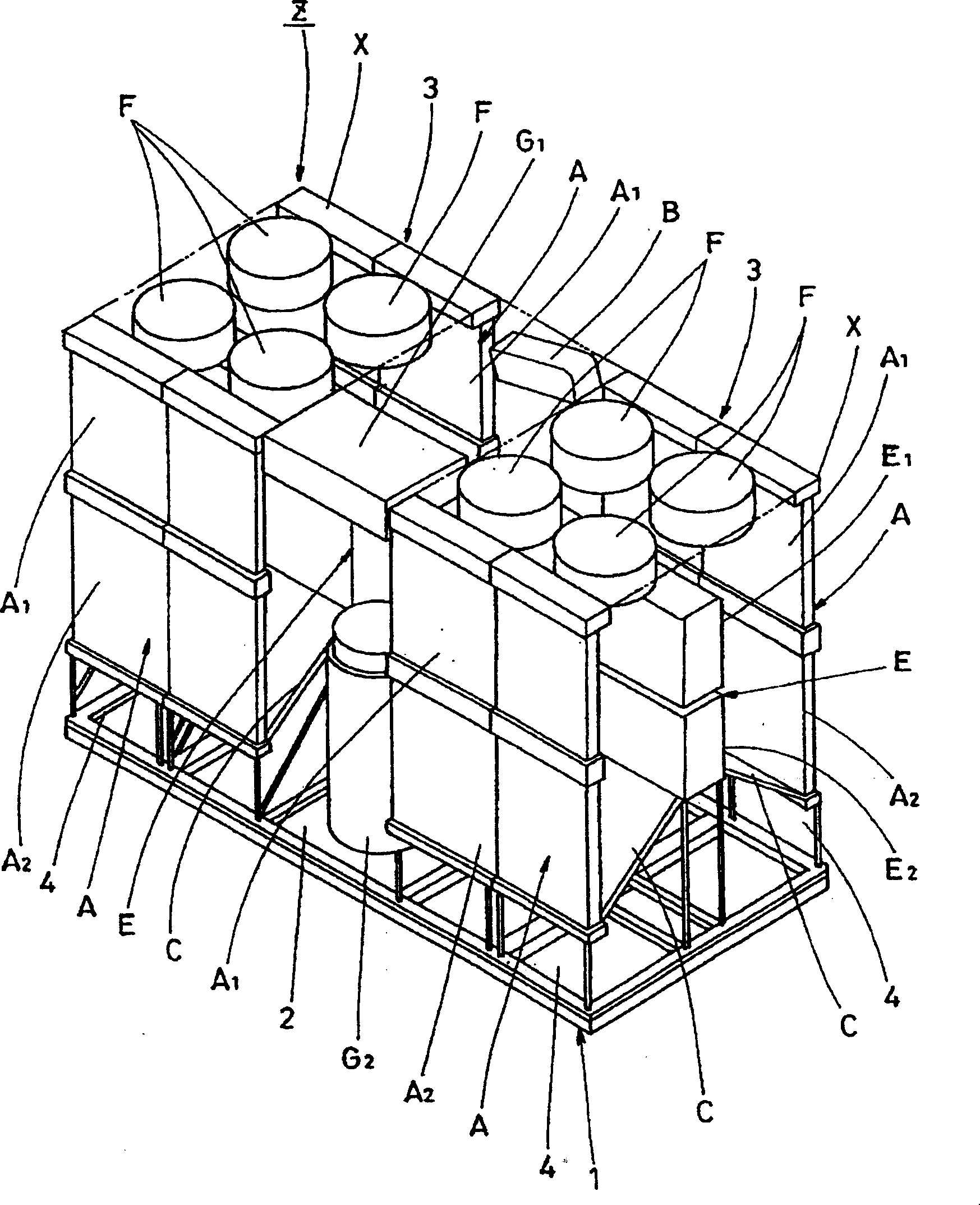
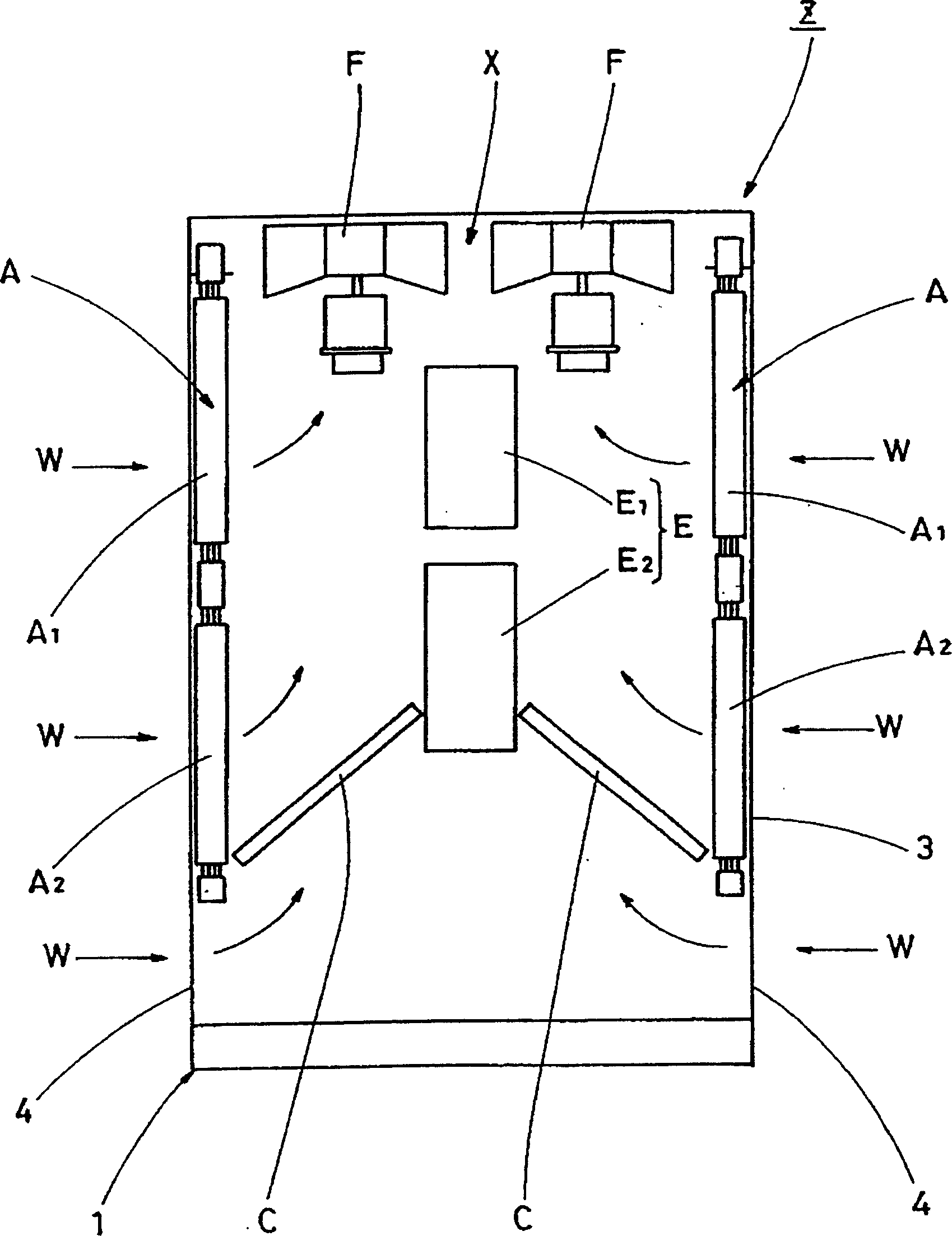
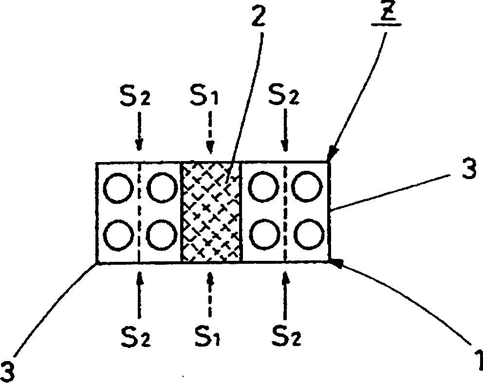
[0035] This air-cooled absorption freezer, such as figure 1 and figure 2 As shown, it includes: a machine room 2 located in the center of the longitudinal direction of the approximately cuboid device body 1 and air cooling and heat exchange parts 3 and 3 arranged on both sides of the machine room 2 in the longitudinal direction.

[0036] In the above-mentioned machine room 2, there are disposed: a high-temperature regenerator G2 located at the lower stage on one side of the device body 1, a low-temperature regenerator G1 located at the upper stage, and a heating chamber located at the upper stage on the other side of the device body 1. heat exchanger B. And, between this machine room 2 and the air cooling and heat exchanging parts 3, 3, although not shown in the figure, a partition wall is provided. This facilitates maintenance of...


PUM


Abstract

In an air-cooled two-stage absorption type refrigerating plant, a plant main body (1) is provided in its longitudinal middle with a machine chamber (2) having a high-temperature regenerator (G2), a low-temperature regenerator (G1) and a heating-purpose heat exchanger (B). The machine chamber (2) is provided on its longitudinal opposite sides with air-cooled heat exchange sections (3, 3) each having an air-cooled heat exchange unit (X) consisting of air-cooled absorbers (A, A), an air-cooled condenser (C) disposed between the lower ends of the air-cooled absorbers (A, A) and fans (F) disposed in the upper region between the air-cooled absorbers (A, A), and an evaporator (E) disposed substantially in the middle between the air-cooled absorbers (A, A). As a result, the air-cooled heat exchange sections (3, 3) are positioned on opposite sides of the machine chamber (2).

Description

technical field [0001] The invention relates to an air-cooled absorption refrigeration device. Background technique [0002] The conventional air-cooled absorption refrigeration device is formed by forming an air suction port on three sides of a cube-shaped device body. In order to make it correspond to it, two air-cooled absorbers and an air-cooled condenser are arranged, and an air-cooled condenser is placed above the center. It is constructed by installing a fan. With this configuration, the heat transfer area of ​​the air-cooled absorber and the air-cooled condenser is ensured as large as possible (for example, refer to JP-A-1-225868). [0003] In addition, in the case of the air-cooled absorption refrigeration device with the above-mentioned structure, the air sucked in by the fan from the air inlet formed on three sides passes through the air-cooled absorber and the air-cooled condenser, effectively cooling the absorption liquid and the refrigerant vapor. Afterwards,...

Claims


Application Information

Patent Timeline
Patent Type & Authority Patents(China)
IPC IPC(8): F25B15/00F25B35/00F25B37/00
CPCF25B35/00Y02B30/62F25B37/00F25B15/008Y02A30/27
Inventor 大平晋谷口圭仁奥田则之安尾晃一药师寺史朗川端克宏河合满嗣植田裕树谷本启介
Owner DAIKIN IND LTD
Why Eureka
Try Eureka