Air-gap axial generator

An axial air gap, power generation device technology, applied in the direction of electromechanical devices, electrical components, magnetic circuit shape/style/structure, etc. Reduce the time for alignment and bearing installation alignment, and the effect of isolating corrosion

Inactive Publication Date: 2007-01-10
傅明华 +1
View PDF1 Cites 0 Cited by
  • Summary
  • Abstract
  • Description
  • Claims
  • Application Information

AI Technical Summary

Problems solved by technology

[0007] 1. It is more difficult to assemble: since the rotor shaft is installed at the center line of the ring-shaped induction coil, the permanent magnet and the induction coil must be kept at a certain distance to form a radial air gap and the permanent magnet must follow the shaft. Rotation requires at least two or more bearings to support the mandrel in the assembly of the mandrel. Therefore, regardless of the distance between the assembled bearings or the permanent magnet and the induction coil, it needs to be aligned very precisely. If there is a slight deviation, when the mandrel rotates Eccentric rotation may occur during the operation, causing damage to the power generation device or severe vibration damage
[0008] 2. High cost: Due to the increase in the number of bearings used and the man-hours and manpower spent on assembly and positioning, a certain amount of manufacturing costs will be incurred

Method used


Image

  • Air-gap axial generator
  • Air-gap axial generator
  • Air-gap axial generator

Examples


Embodiment Construction

[0021] The magnetic induction effect generated by the interaction between the magnetic field and the electric field was discovered by Faraday. Faraday found that when the conductor cuts the magnetic force line, that is, when the conductor passes through the magnetic force line, the conductor will generate an induced electromotive force.

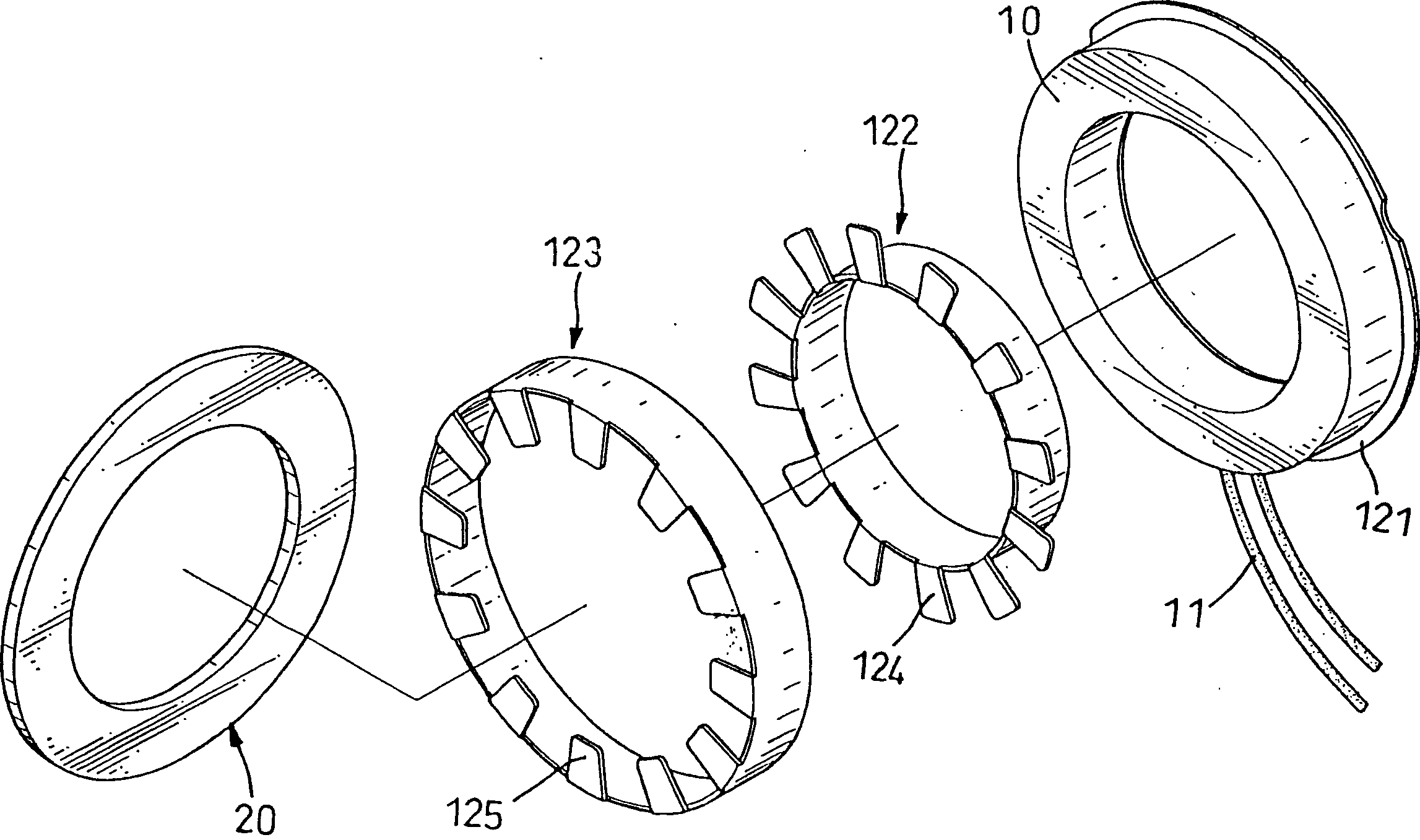
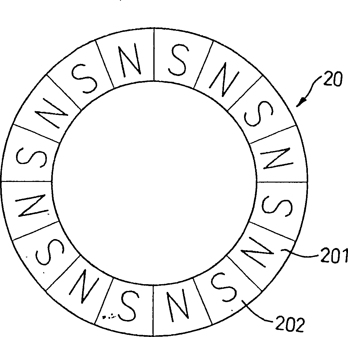
[0022] Such as figure 1 , figure 2 As shown, based on the above principles, the present invention includes an induction coil 10 , a coil base 12 for accommodating the induction coil 10 and a magnet structure 20 .

[0023] The induction coil 10 is formed by winding a conductive coil to form an annular ring, which leads to two conductive wires 11 .

[0024] The coil base 12 includes a base 121 disposed on one side of the induction coil 10 , an inner pole cover 122 and an outer pole cover 123 respectively sleeved on the inner and outer edges of the induction coil 10 .

[0025] The base 121 is an annular thin disk made of metal material. The ...


PUM


Abstract

A axial air gap generate electricity device, includes: induction coil, coil base and magnet structure set on exterior of the induction coil; the induction coil is the ring circled by conductor with two leading wire; the induction coil is set in coil base, and makes two leading wire threads out the coil base; the complex numbers of N pole and S pole arranged in staggering ring is set in the magnet structure; one side of coil base forms induction side; the magnet structure is set in position opposite to the induction side of coil base, and keeps proper distance which forms axial air gap, with induction side.

Description

technical field [0001] The invention belongs to a motor, in particular to an axial air gap type power generation device. Background technique [0002] At present, the existing power generation devices all use the principle of interaction between electricity and magnetism, which includes a rotor and a stator. [0003] Usually, the stator is provided with a ring-shaped induction coil wound by wires, and two wires are connected outside the induction coil to conduct the current generated by the wires of the induction coil to an external electrical device. [0004] The rotor includes permanent magnets with a plurality of magnetic poles and a spindle. [0005] There are a plurality of magnetic poles on the permanent magnet, which are circularly distributed on the mandrel in a staggered arrangement of N pole-S pole-N pole-S pole, and the mandrel is installed on the axis centerline of the induction coil, so that The magnetic poles of the permanent magnet maintain a certain distanc...

Claims


Application Information

Patent Timeline
Patent Type & Authority Patents(China)
IPC IPC(8): H02K21/00H02K21/02H02K21/26H02K1/17
Inventor 邱春诚
Owner 傅明华
Why Eureka
Try Eureka