
Air compressor

An air compressor, compression chamber technology, applied in the direction of electromechanical devices, electrical components, mechanical equipment, etc., can solve the problems of increasing working hours, increasing costs, and inability to suppress fluctuations, and achieve the effect of suppressing fluctuations

Active Publication Date: 2007-01-24
NITTO KOHKI CO LTD
View PDF6 Cites 0 Cited by
  • Summary
  • Abstract
  • Description
  • Claims
  • Application Information

AI Technical Summary

Problems solved by technology

[0006] In Patent Document 1, since a separate air storage tank is provided to temporarily store and discharge air to the air storage tank, the fluctuation of the air can be suppressed, but at this time, if the volume of the air storage tank is not made large to a certain extent, it still cannot Suppressing fluctuations
[0007] In addition, there is a problem of not only increasing the number of parts constituting the air storage tank and the number of parts connecting the air storage tank and the compressor, but also increasing the man-hours for its assembly and increasing the cost.

Method used


Image

  • Air compressor
  • Air compressor
  • Air compressor

Examples


Embodiment Construction

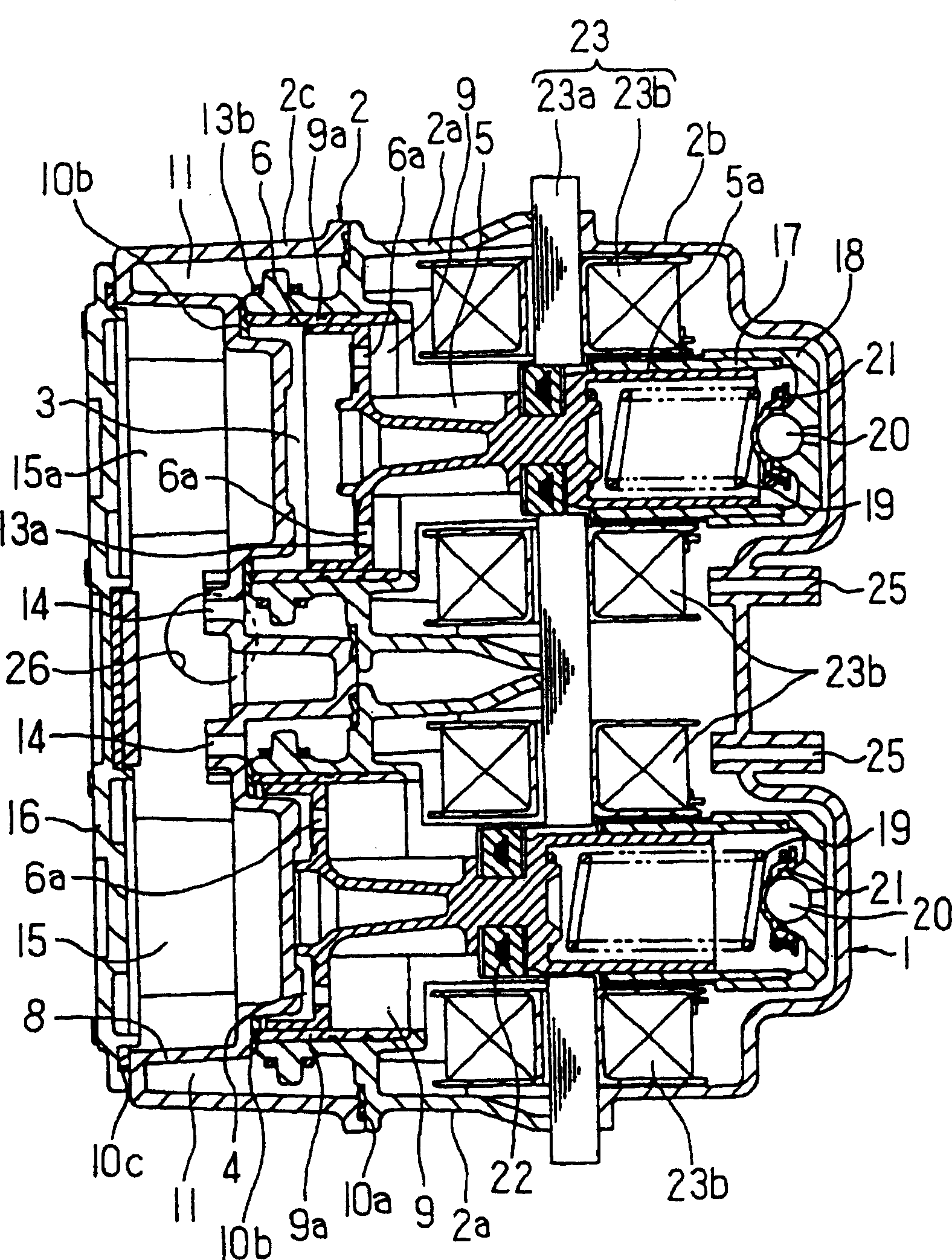
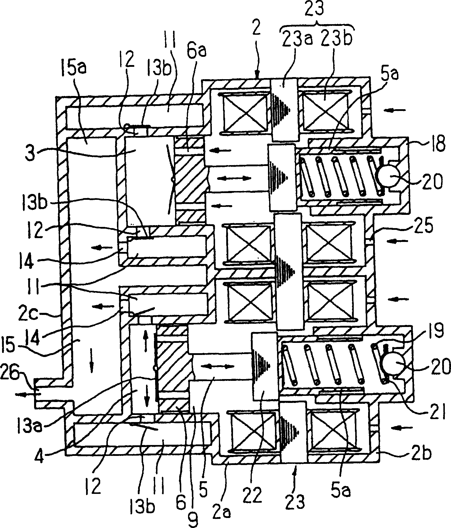
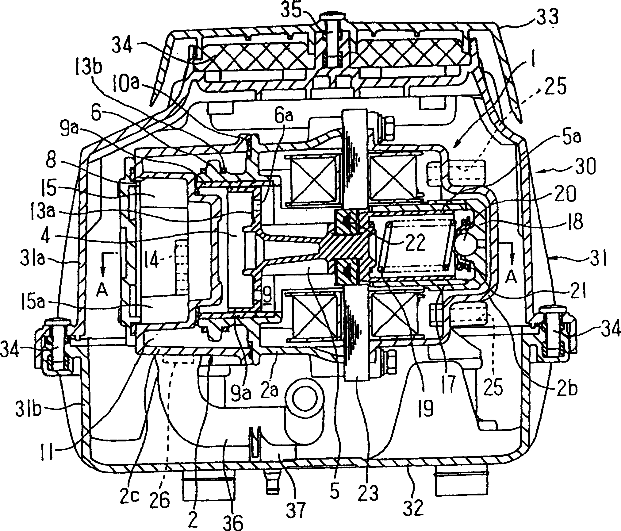
[0013] An example of an air compressor according to the present invention, which is applied to an electromagnetic reciprocating compressor, will be described with reference to the drawings.

[0014] figure 1 It represents the cross-section of the electromagnetic reciprocating compressor, which will be described later image 3 A-A line sectional view of figure 2 yes figure 1 schematic illustration of . In the figure, 1 is a compressor main body, 2 is the casing of the compressor main body 1, and this casing 2 is comprised by the front part case 2a, the rear part case 2b, and the top cover 2c. In the casing 2, a cylinder 9 formed of a cylindrical liner 9a is provided inside the compressed air discharge side, and a top cover 6, which is a front side of a piston (compressor) 5, is slidably fitted into the cylinder 9. A plurality of through-holes 6a are suitably provided in the circumferential direction on the top cover 6, and an openable valve 13a is provided on the side of t...


PUM


Abstract

Provided is an air compressor provided with an air tank as one body with a compressor main body, capable of efficiently suppressing pulsation without reducing a delivery air quantity, of reducing the count of parts constructing the air compressor, of simplifying assembly work, and of enabling miniaturization. In this air compressor, the air tank part 15 for suppressing the pulsation of delivery air is provided as one body on the compressor main body 1 including compression chambers 3, 4 for compressing air by the reciprocating motion of a compressing body 5 and a delivery chamber 11 for delivering air from the compression chambers 3, 4.

Description

technical field [0001] The present invention relates to an air compressor, and more particularly to an air compressor capable of downsizing a compressor using an electromagnetic reciprocating compressor, etc., without reducing the amount of air discharged, and reducing fluctuations in discharged air as much as possible. Background technique [0002] Such an air compressor is known to use compressed air such as an electromagnetic reciprocating compressor as an example of a compression drive source, and the compressed air is discharged to the outside through a separate air storage tank. [0003] The inventors of the present invention have proposed a compressor having a structure in which an air storage tank for buffering temporarily storing the compressed air discharged from the compressor is provided in order not to transmit the fluctuation of the air discharged from the compressor to the outside, and It is installed separately from the compressor, and the compressed air is d...

Claims


Application Information

Patent Timeline
Patent Type & Authority Patents(China)
IPC IPC(8): F04B35/04F04B39/00F04B39/12F04B41/02
CPCF04B25/005F04B35/04F04B39/0027F04B39/121F04B39/14H02K41/031
Inventor 御器谷俊雄田辺政昭
Owner NITTO KOHKI CO LTD
Learn More