Disk drive incorporating vibration suppressing mechanism

An optical disc drive, optical disc technology, applied in vibration suppression adjustment, rotational vibration suppression, electromechanical devices, etc., can solve the problems of difficulty in leaving the sphere 13, reading errors, etc., and achieve the effect of reducing the effect of eccentricity

Inactive Publication Date: 2001-05-30
PANASONIC CORP
View PDF1 Cites 1 Cited by
  • Summary
  • Abstract
  • Description
  • Claims
  • Application Information

AI Technical Summary

Problems solved by technology

[0022] In this way, after reading ordinary numbers with high-speed rotation, under the situation of changing to audio work immediately, due to the characteristics that the ball 13 is difficult to leave the wall 20 and is difficult to be sucked by the wall 26, after starting to read the audio data, the ball 13 is held. The wall 26 sucks, and the impact of sucking is transmitted to the optical disc 1, which may become the main cause of reading errors.
[0023] In addition, when the disc starts to rotate, that is, when the rotation speeds up, it is difficult for the ball 13 to leave the wall 26 due to the effect of the large leakage magnetic flux 24.

Method used


Image

  • Disk drive incorporating vibration suppressing mechanism
  • Disk drive incorporating vibration suppressing mechanism
  • Disk drive incorporating vibration suppressing mechanism

Examples


Embodiment 1

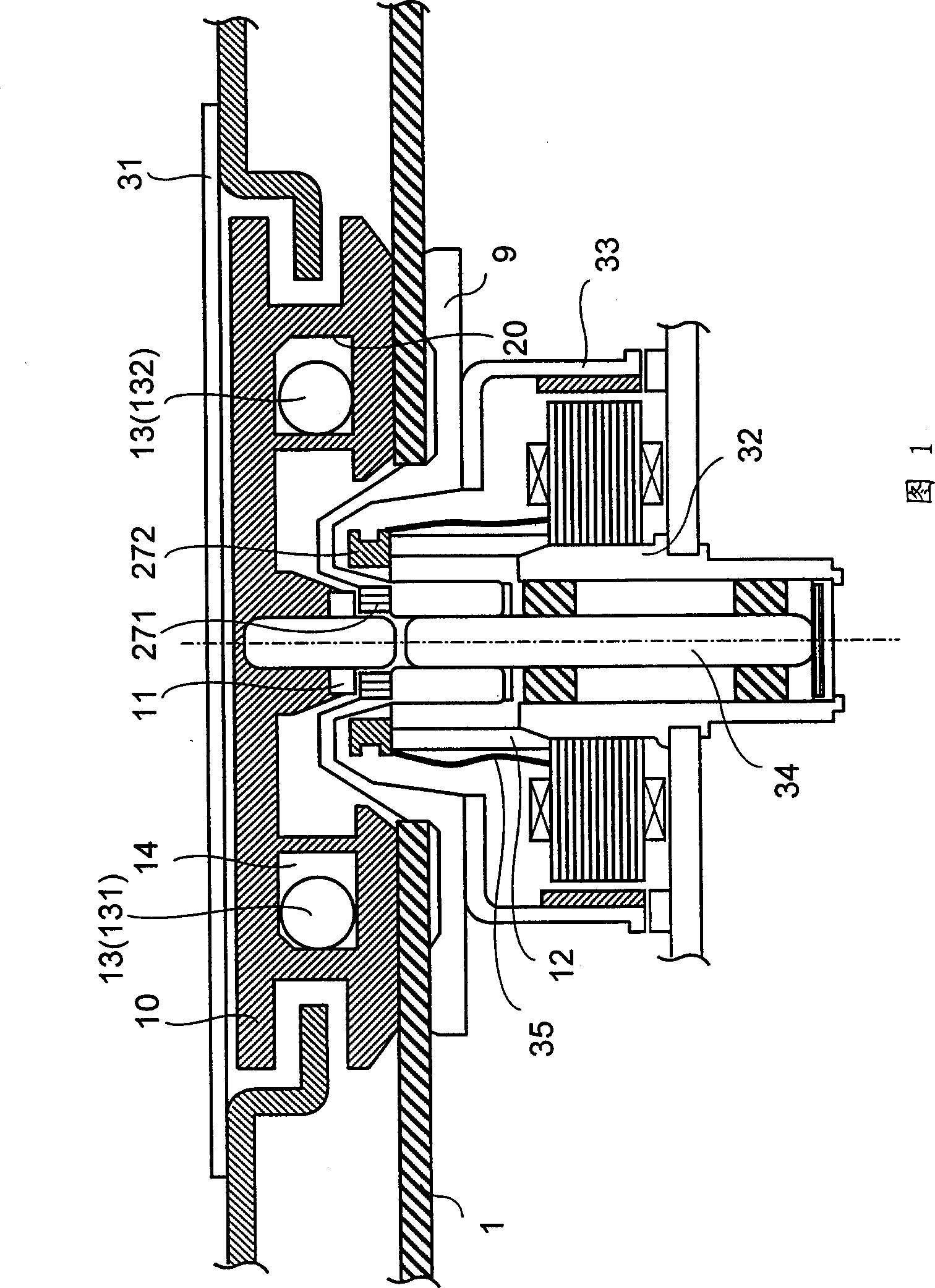
[0040] Fig. 1 is a side sectional view of the main part of an optical disk drive device according to Embodiment 1 of the present invention, showing an example in which an electromagnet is arranged on a fixed part of a spindle motor.

[0041] Components having functions similar to those of the above conventional examples use the same symbols.

[0042] In this example 1, with Figure 6 The disc drive device of the conventional example shown is different in the following points.

[0043] Magnet 271 is smaller than existing ones, and is located on the turntable. A yoke 11 is provided on the clamp 10, and the yoke 11 and the magnet 271 face each other through a gap. The optical disk 1 is clamped between the clamper 10 and the turntable 9 by the attractive force between the magnet 271 and the yoke 11 . In addition, the electromagnet 272 is operated to eliminate the imbalance of the optical disk 1, and this electromagnet is used as a magnetic generator for electromagnetic conversi...

Embodiment 2

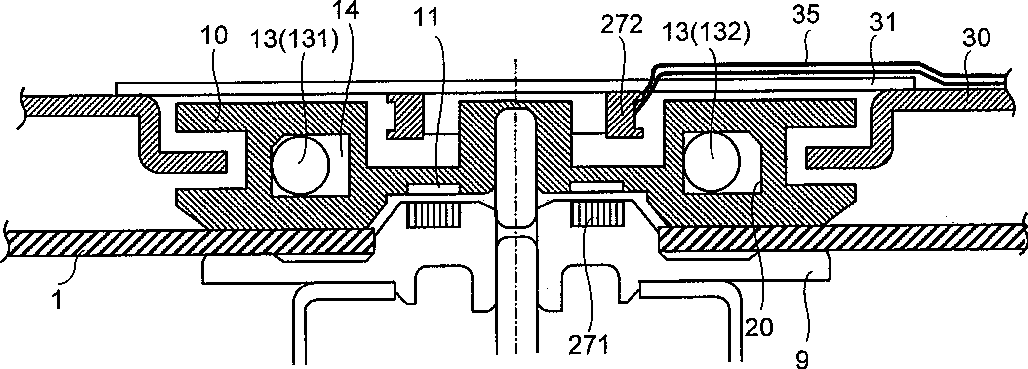
[0054] figure 2 It is a side sectional view of main parts of an optical disk drive device according to Embodiment 2 of the present invention, and is an example in which an electromagnet is provided on a stopper protection plate.

[0055] Figure 4A It is a diagram showing the change of the rotational speed of the disc with time when the disc changes from low speed to high speed, and a pulse waveform diagram showing the corresponding change of the duty of the pulse applied to the electromagnet with time, Figure 4B It is a graph showing the change with time of the rotational speed of the disc when the disc changes from high speed to low speed, and a pulse waveform showing the change with time of the duty of the pulse applied to the electromagnet corresponding thereto.

[0056] figure 2 Among them, the retainer protection plate 31 is arranged on the upper part of the retainer 10 . The cylindrical electromagnet 272 is fixed on the lower side of the retainer protection plate ...


PUM


Abstract

A disk drive is provided with a balancer having a hollow circular section (14) that accommodates a magnetic body (13), a clamper (10) that rotates integrally with the disk (1), a magnetism generating device (272) that generates a magnetic flux for coupling with the magnetic body (13) by electromagnetic conversion, and a controller that controls the output from the magnetism generating device (272). By incorporating such a vibration suppressing mechanism, imbalance during disk rotation is canceled and a read error is suppressed when the speed is changed and spinup occurs.

Description

technical field [0001] The present invention relates to an optical disk drive device capable of stably recording and / or reproducing by incorporating a vibration suppressing mechanism for suppressing the optical disk, which is a medium such as a CD-ROM drive device or a CD-R drive device. Self-vibration due to imbalance. technical background [0002] In recent years, the data transmission speed of an optical disk drive device for recording and / or reproducing data such as a CD-ROM drive device or a CD-R drive device has rapidly increased. In order to transfer data at high speed, it is necessary to rotate the optical disk at high speed. [0003] Generally, an unbalanced optical disc with uneven quality is often produced due to the uneven thickness of the optical disc, and when such an optical disc is rotated at a high speed, the following disadvantages occur. That is, the unbalanced force of the optical disk will generate self-vibration, and the vibration will be transmitted ...

Claims


Application Information

Patent Timeline
Patent Type & Authority Applications(China)
IPC IPC(8): F16F15/18F16F15/36G11B17/028G11B19/20G11B33/08H02K7/04H02K29/00
CPCG11B19/2009G11B17/0284G11B19/2027F16F15/18F16F15/363F16F2222/06G11B33/08G11B19/02G11B2220/2545
Inventor 神户真一
Owner PANASONIC CORP
Why Eureka
Try Eureka