Rotor brake of rotating reel

A technology of braking device and reel, which is applied to fishing reel, fishing, application, etc., can solve the problems of reducing the swing angle of the connecting rod and weakening the force, and achieve the effect of smooth movement

Inactive Publication Date: 2007-02-07
SHIMANO INC
View PDF3 Cites 4 Cited by
  • Summary
  • Abstract
  • Description
  • Claims
  • Application Information

AI Technical Summary

Problems solved by technology

Therefore, the force transmitted from the shaft member to the guide ring support arm through the link will reduce the swing angle

Method used


Image

  • Rotor brake of rotating reel
  • Rotor brake of rotating reel
  • Rotor brake of rotating reel

Examples


Embodiment Construction

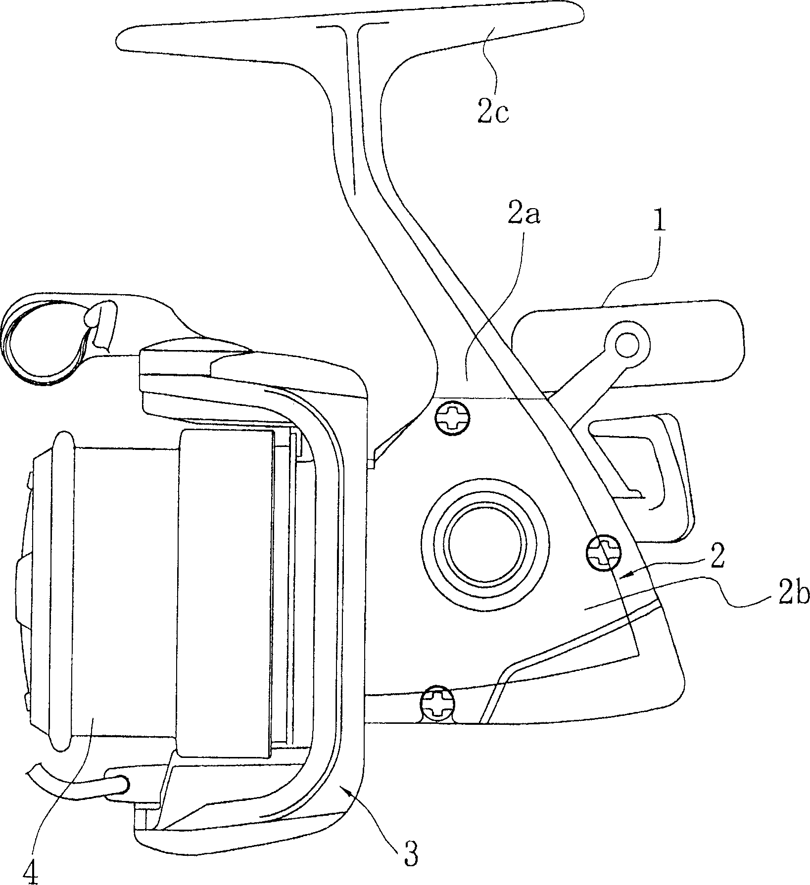
[0047] figure 1 Among them, a spinning reel according to an embodiment of the present invention has a handle 1 , a reel body 2 supporting the handle 1 rotatably, a rotor 3 , and a cord reel 4 . The rotor 3 is rotatably supported on the front of the cord reel body 2 . The line reel 4 reels the fishing line on the outer peripheral surface, and is arranged at the front portion of the rotor 3 so as to be able to move back and forth freely.

[0048] The cord reel body 2 has a cord reel case 2a including an inner space, and a cover member 2b detachably attached to the cord reel case 2a for blocking the space of the cord reel case 2a.

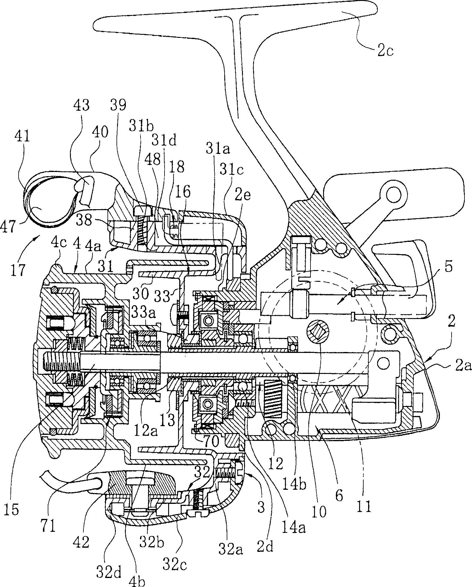
[0049] The reel case 2a is made of, for example, a magnesium alloy, and a T-shaped pole attachment leg 2c extending forward and backward is integrally formed on the upper part. As shown in FIG. 2, a rotor driving member 5 that rotates the rotor 3 in conjunction with the rotation of the handle 1 is provided in the space of the reel housing 2a, and a ...


PUM


Abstract

Rotor braking device(54)-which is for braking the rotor (3), fitted rotatively to a spinning-reel reel unit (2), in response to pivoting of the bail arm (17) that pivots between line-winding and line-releasing postures-includes a braking member (65) and a shifting member (51). The elastic braking member (65) is provided on front of the reel unit facing the rotor, and includes, in at least a portion of its contour, a braking surface (65a) and a conducting surface (65b) arranged in continuation with the braking surface, extending frontward from the braking surface and gradually receding from the braking surface. The shifting member is disposed on the rotor and can be shifted in a direction perpendicular to a pressure direction of the braking member, such that when the bail arm pivots from the line-winding posture to the line-releasing posture, the shifting member contacts first the conducting surface and then the braking surface.

Description

technical field [0001] The present invention relates to a braking device, in particular, based on the swing of a guide ring support arm that swings an upper rotor rotatably mounted on a cord reel body of a rotary cord reel between a cord winding position and a line releasing position. Rotor braking device for braked spinning reels. Background technique [0002] Generally, the rotor of the spinning reel is provided with a guide ring support arm for guiding the fishing line to the reel. The guide ring support arm adopts: the line winding posture that guides the fishing line toward the outer periphery of the reel when winding the fishing line, and the line releasing posture that falls from the winding posture without hindrance when the fishing line is unwound from the line reel . A guide ring reversing device is provided on the rotor to maintain the guide ring support arm in the winding position and the releasing position, and to return from the releasing position to the wind...

Claims


Application Information

Patent Timeline
IPC IPC(8): A01K89/01A01K89/015
CPCA01K89/0108A01K89/015
Inventor 佐藤纯
Owner SHIMANO INC
Why Eureka
Try Eureka