Improvements to spiral heat exchangers

A heat exchanger, spiral technology, applied in the field of spiral heat exchangers, can solve problems such as difficult operation, and achieve the effect of simplified methods

Inactive Publication Date: 2007-02-07
SPIREC
View PDF8 Cites 2 Cited by
  • Summary
  • Abstract
  • Description
  • Claims
  • Application Information

AI Technical Summary

Problems solved by technology

This welding operation therefore constitutes a difficult operation which must be carried out with manual means

Method used


Image

  • Improvements to spiral heat exchangers
  • Improvements to spiral heat exchangers
  • Improvements to spiral heat exchangers

Examples


Embodiment Construction

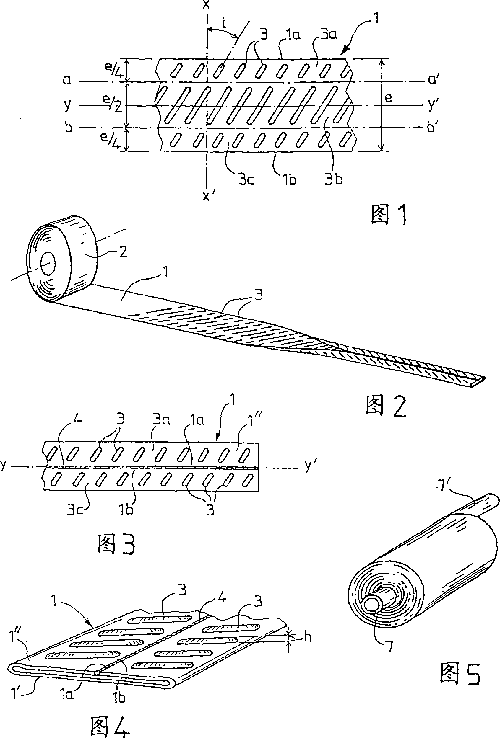
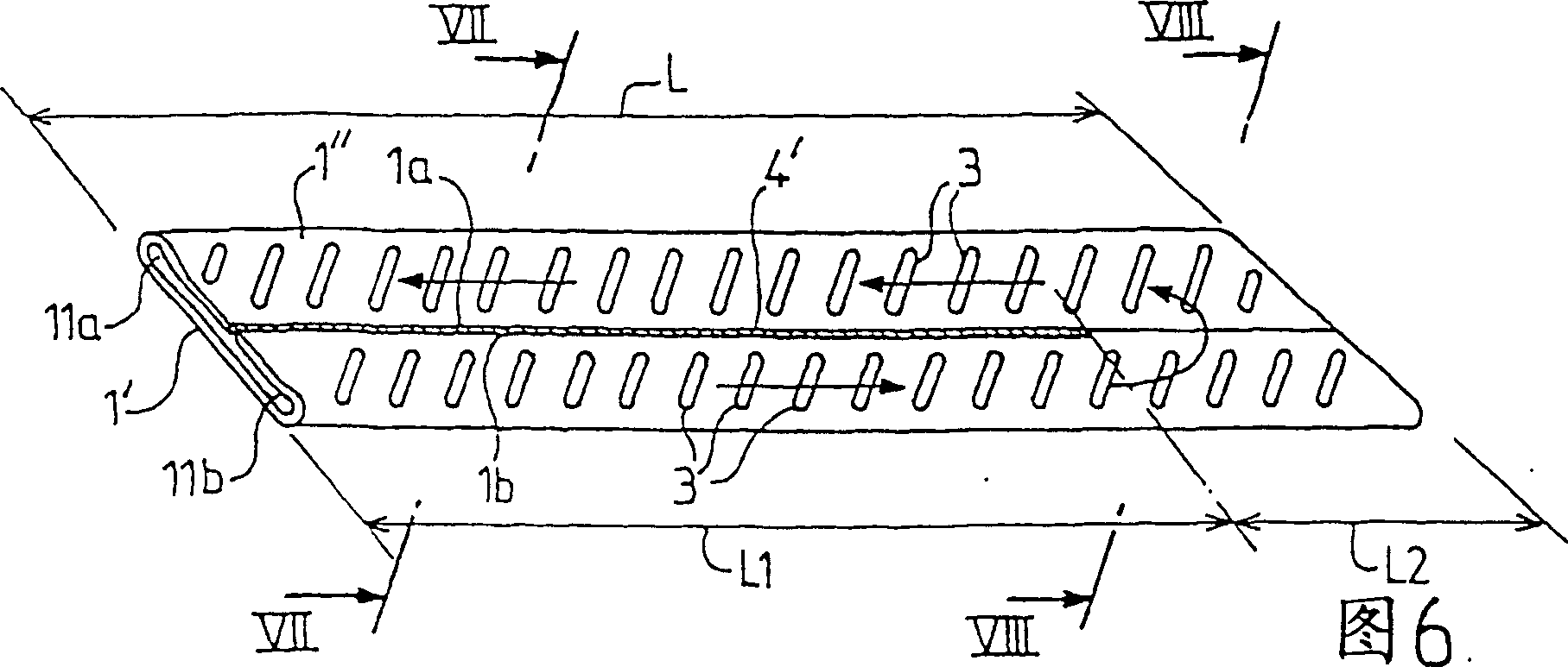
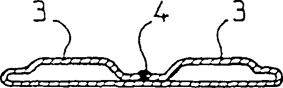
[0029] The spiral metal heat exchanger according to the invention is constructed starting from a metal sheet 1 , in particular made of stainless steel sheet metal, which is supplied to the user in the form of a sheet coil 2 . Each reinforcing rib 3 is formed on the metal plate 1, and these reinforcing ribs 3 are obtained by press forming. These stiffeners 3 form an angle of attack with the transverse axis XX' of the metal sheet 1 i , in this example, the angle of attack i About 45°. Each reinforcing rib 3 is distributed on three lateral areas, that is, a length substantially equal to the width of the metal sheet 1 e A quarter of the first transverse zone 3a, a length substantially equal to the width of the metal sheet 1 e half of the central region 3b, and a length substantially equal to the width of the metal sheet 1 e A quarter of the third lateral zone 3c. The height of these ribs 3 h Equal to half of the space desired to be provided between the spiral wound layers at...


PUM


Abstract

The invention concerns a spiral heat exchanger, consisting of a series of spiral plates spaced apart from one another by spacer elements (3), wherein the spiral plates are formed by a coiled flattened tubular element and consisting of at least a sheet of material (1) whereof the edges (1a, 2b) are sealingly assembled by linking means (4) which extend parallel to the longitudinal axis (yy') of the sheet (1) Said exchanger is characterised in that the flattened tubular element comprises on its outer surfaces ribs (3) inclined relative to its transverse axis (XX').

Description

technical field [0001] The present invention relates to heat exchangers, and in particular to heat exchangers intended to ensure heat exchange between two fluids which must be separated from each other, for example of the spiral type produced by winding metal plates. Background technique [0002] Heat exchangers of this type are known to consist of a bent plate which is itself bent into a coil. Spacer elements are placed between the different coils of the heat exchanger during the coiling phase to space the plates apart from each other to allow fluid flow between the coils. The ends of the heat exchanger and the edges of the plates forming the spiral must therefore be sealed, usually by solder waves. This heat exchanger is therefore composed of two separate circuits in which fluids - especially liquids - can flow, i.e. one circuit is the space sandwiched between the different coils and the other circuit is the space sandwiched between the two bent walls of each spiral. ...

Claims


Application Information

Patent Timeline
Patent Type & Authority Patents(China)
IPC IPC(8): F28D9/04F28F3/04B21D53/04F28D1/03
CPCF28D9/04F28D1/0391Y02P80/10
Inventor 让-马里耶·盖盖恩
Owner SPIREC
Why Eureka
Try Eureka