Liquid cooling radiator

A cooling device and liquid cooling technology, which is applied in the direction of instruments, electrical digital data processing, electrical components, etc., can solve the problems of difficult system configuration and increased radiator volume, and achieve the effect of compact structure and easy configuration of the cooling device

Inactive Publication Date: 2007-02-21
HONG FU JIN PRECISION IND (SHENZHEN) CO LTD +1
View PDF6 Cites 2 Cited by
  • Summary
  • Abstract
  • Description
  • Claims
  • Application Information

AI Technical Summary

Problems solved by technology

However, the pump, heat sink, and condensing pipeline of this water-cooled radiator are independent, and external pipelines are required to connect the accessories to form a circulation system, which increases the volume of the entire radiator and is difficult to match with the system

Method used


Image

  • Liquid cooling radiator
  • Liquid cooling radiator
  • Liquid cooling radiator

Examples


Embodiment Construction

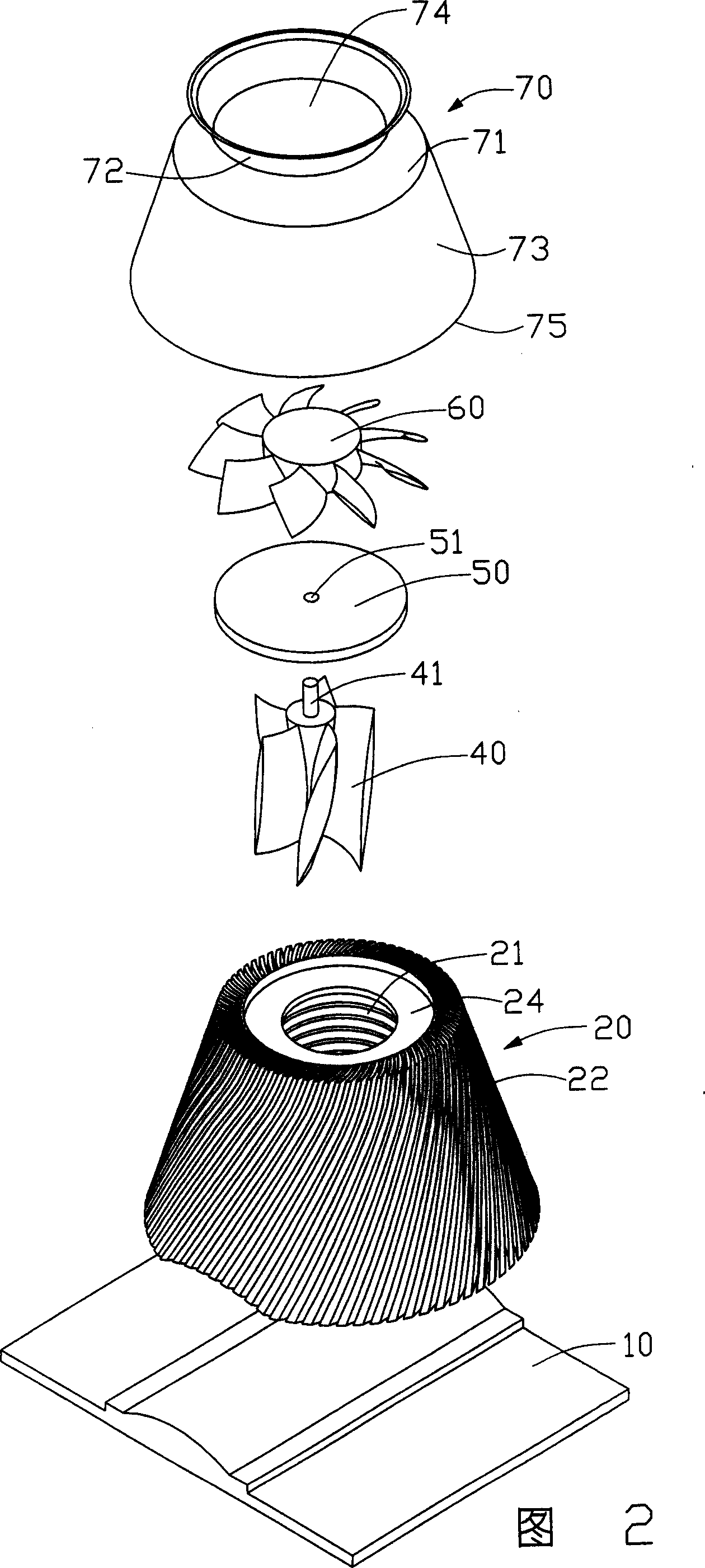
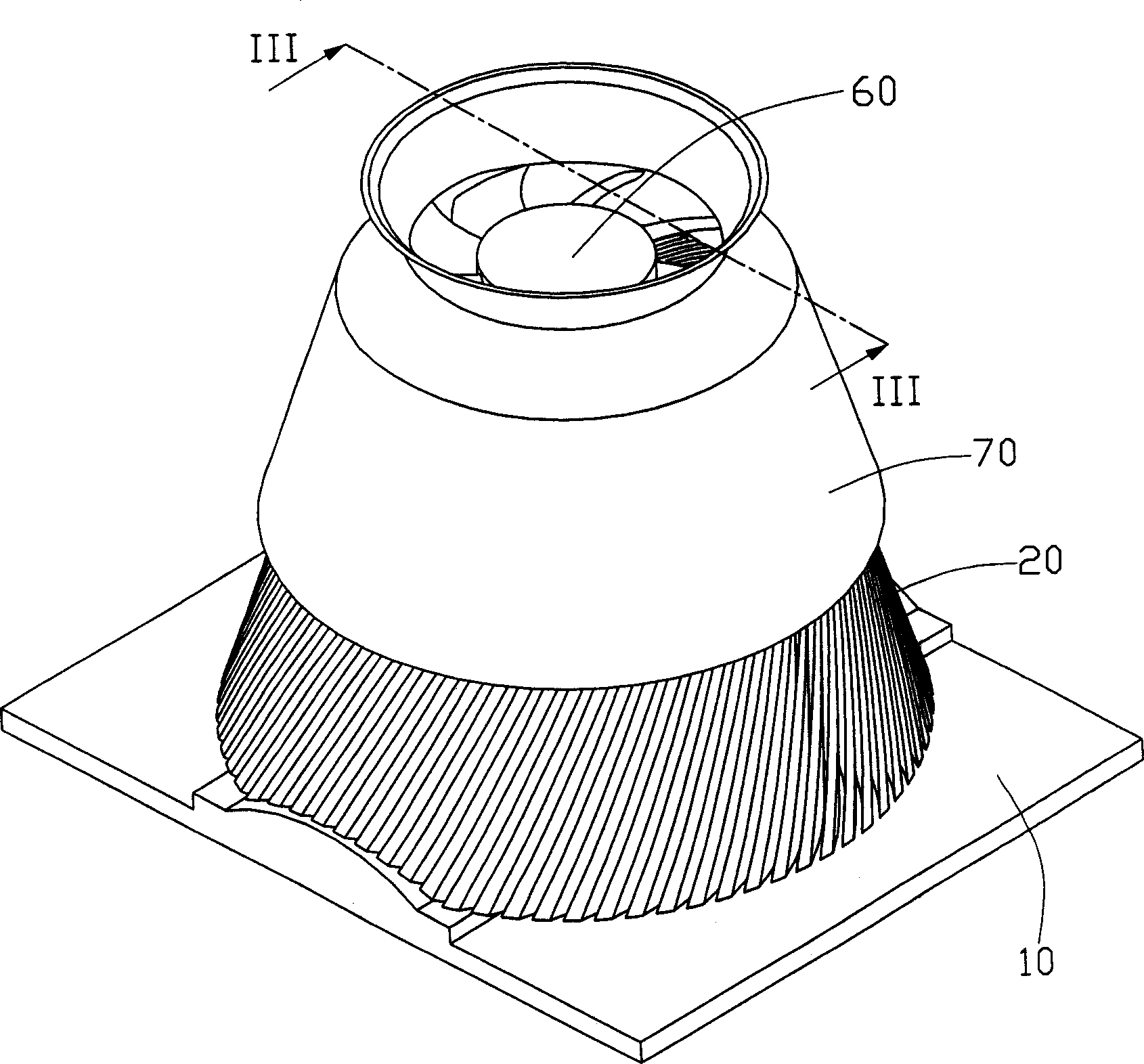
[0016] Please also refer to Figure 2, image 3 and Figure 4 , the liquid-cooled heat dissipation device of the present invention is used to assist electronic components (not shown in the figure) to dissipate heat. It includes a base body 20. A cavity 21 is formed inside the base body 20. The cavity 21 is filled with a working liquid, usually water, and the base body 20, the outer wall surface (not marked) is provided with a plurality of cooling fins 22; a base 10 is used to support the base 20; a liquid cooling fan 40 is extended in the base cavity 21; a connecting plate 50, wherein A through hole 51 is opened therebetween; an air cooling fan 60 is located above the connecting plate 50 and is connected with the liquid cooling fan 40 through the through hole 51 passing through the connecting plate 50 through a shaft 41 ; and a housing 70 .

[0017] The base 10 is flat, with an arc-shaped protrusion (not shown) in the middle, so that the central part where the heat is concentr...


PUM


Abstract

The apparatus is composed of a base body with a cavity filled with working liquid. Extended from the outside wall of the base body, several cooling fans are settle. An agitated apparatus is in the cavity, a cooling fan is on the top of cavity. When operating, the agitated apparatus drives the liquid moving. The heat generated by the electronic items is conducted to the fin and emit to outside through the cooling fan.

Description

【Technical field】 [0001] The invention relates to a liquid-cooled heat dissipation device, in particular to a liquid-cooled heat dissipation device with good heat dissipation effect and compact structure. 【Background technique】 [0002] With the rapid development of the information industry, the calculation speed of the computer central processing unit (CPU) is getting faster and faster, and the heat generated by it is also increasing. If the excessive heat cannot be removed in time, it will seriously affect the CPU. runtime stability. For this reason, the industry usually uses a combination of an aluminum extruded heat sink and a fan installed on the top surface of the central processing unit to assist in removing heat. However, the commonly used aluminum extruded heat sink can only reach a maximum of 13:1 because of the ratio of the height of the heat sink to the width of the groove between the cooling fins. As the power of the central processing unit continues to rise, ...

Claims


Application Information

Patent Timeline
Patent Type & Authority Patents(China)
IPC IPC(8): H01L23/473G06F1/20
Inventor 李宗隆王东何立汪胜华顾建华刘志刚
Owner HONG FU JIN PRECISION IND (SHENZHEN) CO LTD
Why Eureka
Try Eureka