Sliding-vane rotor engine

A vane rotor and engine technology, applied in combustion engines, machines/engines, internal combustion piston engines, etc., can solve the problems of experimental use, large vibration and noise, and structural asymmetry, and achieve light weight, low vibration, and structure. symmetrical effect

Active Publication Date: 2007-12-12
吴刚
View PDF0 Cites 2 Cited by
  • Summary
  • Abstract
  • Description
  • Claims
  • Application Information

AI Technical Summary

Problems solved by technology

However, it also brings the following more realistic problems at the same time: the overall performance of the stroke engine has less and less room for further improvement.
However, due to defects such as low fuel efficiency, high machining accuracy, asymmetric structure, large vibration and noise, etc., it stopped at the initial stage of a small number of experimental applications.

Method used


Image

  • Sliding-vane rotor engine
  • Sliding-vane rotor engine
  • Sliding-vane rotor engine

Examples


Embodiment Construction

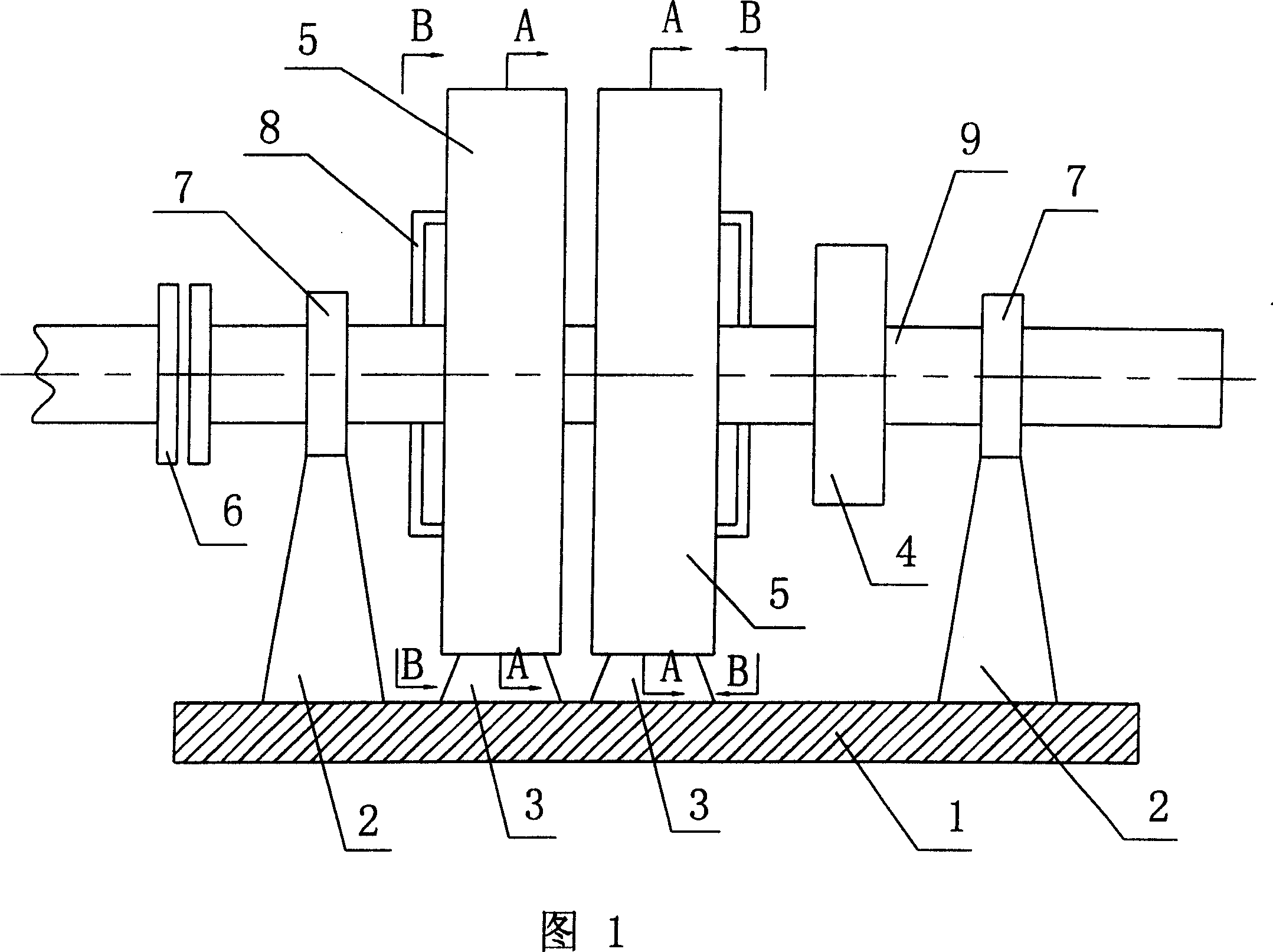
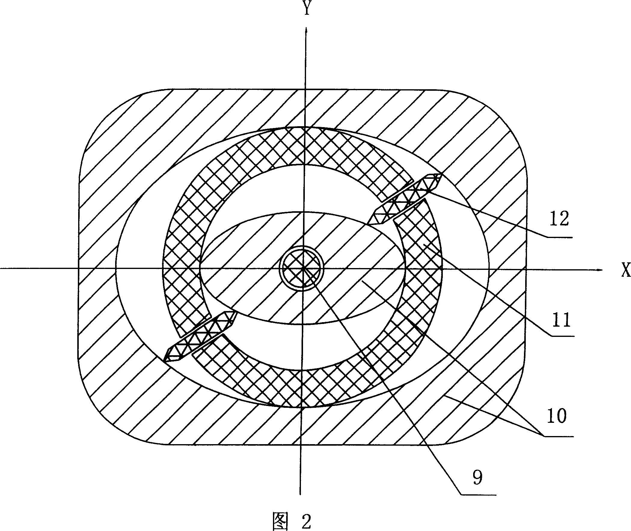
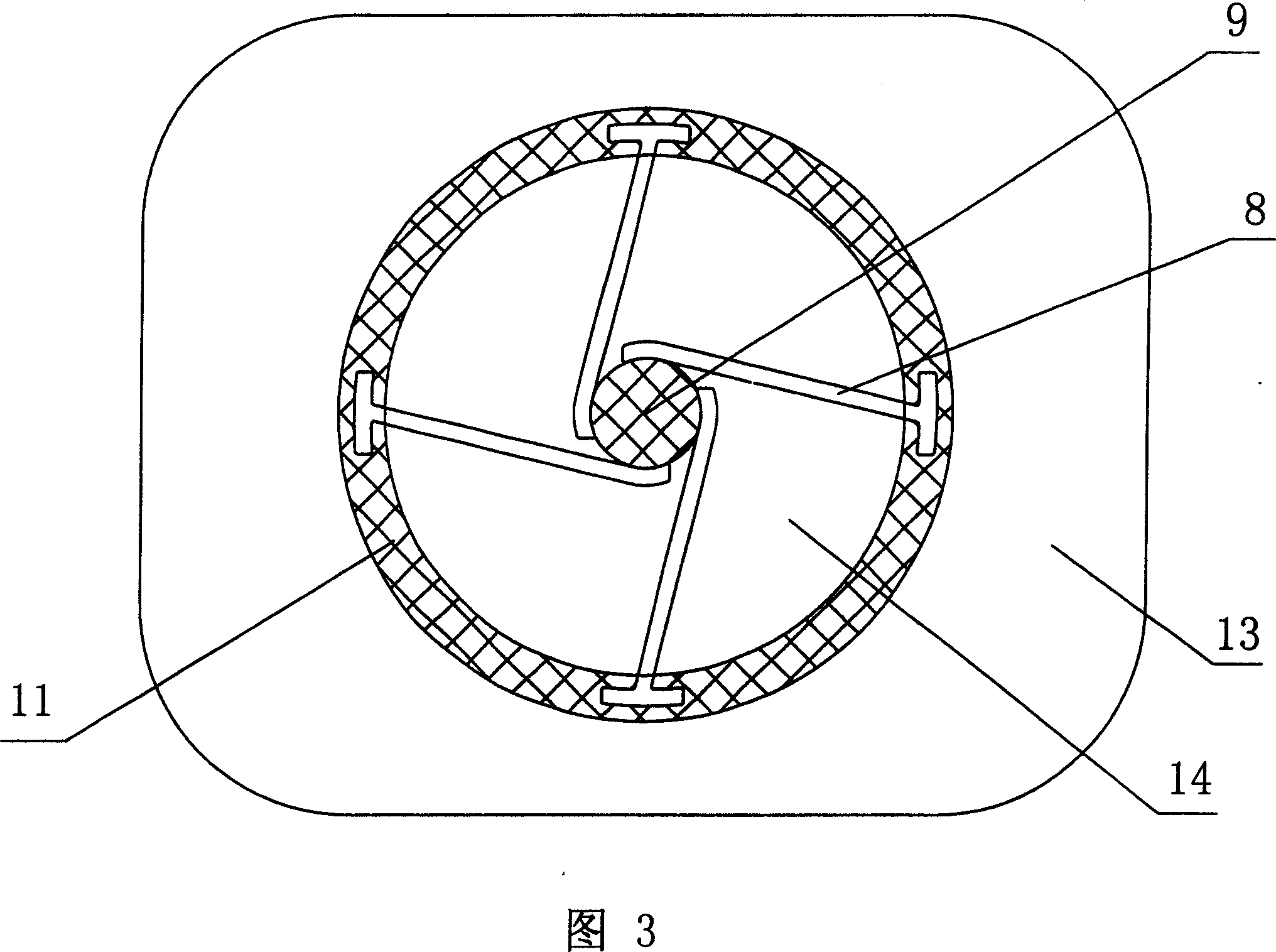
[0017] Referring to Figures 1, 2, and 3, the G·W engine is mounted on the bearing seat 2 of the machine base 1 through the bearing 7 with the rotating shaft 9, and the rotating shaft 9 is mounted on the rotating cylinder 5 supported by the cylinder block 3 and the starter motor. 4. One end of the rotating shaft 9 is matched with the clutch 6, the core component of the G·W single engine is, and the two adjacent rotating cylinders 5 are a coaxial 9 combination. The two rotary cylinders 5 are a power cylinder and a compression cylinder with basically the same structure. The rotor 11 is connected with the rotating shaft 9 through the connecting rib 8, so that the rotor 11 and the shaft 9 are mutually driven to rotate synchronously. It is arranged outside the cylinder 5 side.

[0018] It can be seen from the sectional view of the A-A rotary cylinder and FIG. 4 that there is a nearly elliptical annular cavity between the inner and outer solids of the stator 10 of the rotary cylinde...


PUM


Abstract

The invention discloses a new rotary engine - sliding blade rotor engine ( shortly: G.W engines). there is a nearly oval-shaped ring cavum between the two entities of the engine stator inside and outside, form eight studio after assembly with the circular rotor which has two sliding vane. The eight studios volume continuous change when the rotor rotates, can independent complete the pre-conditions respectively. The advantage is compared with the same power engine, the engine, simple structure, symmetry, small size, light weight, vibration and noise is small in the operation. Less machine parts, easy development and production. It combustion energy directly from the rotational torque. It is a new continuous operation engine.

Description

technical field [0001] The present invention is an internal combustion engine, a new type of rotary engine. Specifically, it is a rotary engine with an embedded sliding vane rotor. It is suitable for developing into gasoline engines, diesel engines, and engines burning various liquid and gas fuels. Background technique [0002] The current application of stroke-type engines has developed many models in different fields and for different purposes. They have different numbers of cylinders, different arrangements, and different displacements. Especially in recent decades, the design and overall performance of stroke-type engines have been quite perfect. It adopts many advanced means such as: fuel electronically controlled injection, electronically controlled ignition, idle speed control, exhaust control, intake control, warning prompt, self-diagnosis, vector effect protection, optimal air-fuel ratio control and so on. However, it also brings the following more realistic pro...

Claims


Application Information

Patent Timeline
Patent Type & Authority Applications(China)
IPC IPC(8): F02B53/02F02B53/08F02B55/16
CPCY02T10/17Y02T10/12
Inventor 吴刚
Owner 吴刚
Why Eureka
Try Eureka