
Metallurgical impact pad

A technology of impact pads and tundishes, which is applied in the field of impact pads and can solve complex problems

Inactive Publication Date: 2007-03-21
FOSECO INT LTD
View PDF7 Cites 3 Cited by
  • Summary
  • Abstract
  • Description
  • Claims
  • Application Information

AI Technical Summary

Problems solved by technology

[0010] The process of designing a new impact pad that meets specific predetermined parameters is extremely complex because changing one aspect of the impact pad design will generally have unpredictable results on the fluid dynamics of the overall tundish system

Method used


Image

  • Metallurgical impact pad
  • Metallurgical impact pad
  • Metallurgical impact pad

Examples


Embodiment Construction

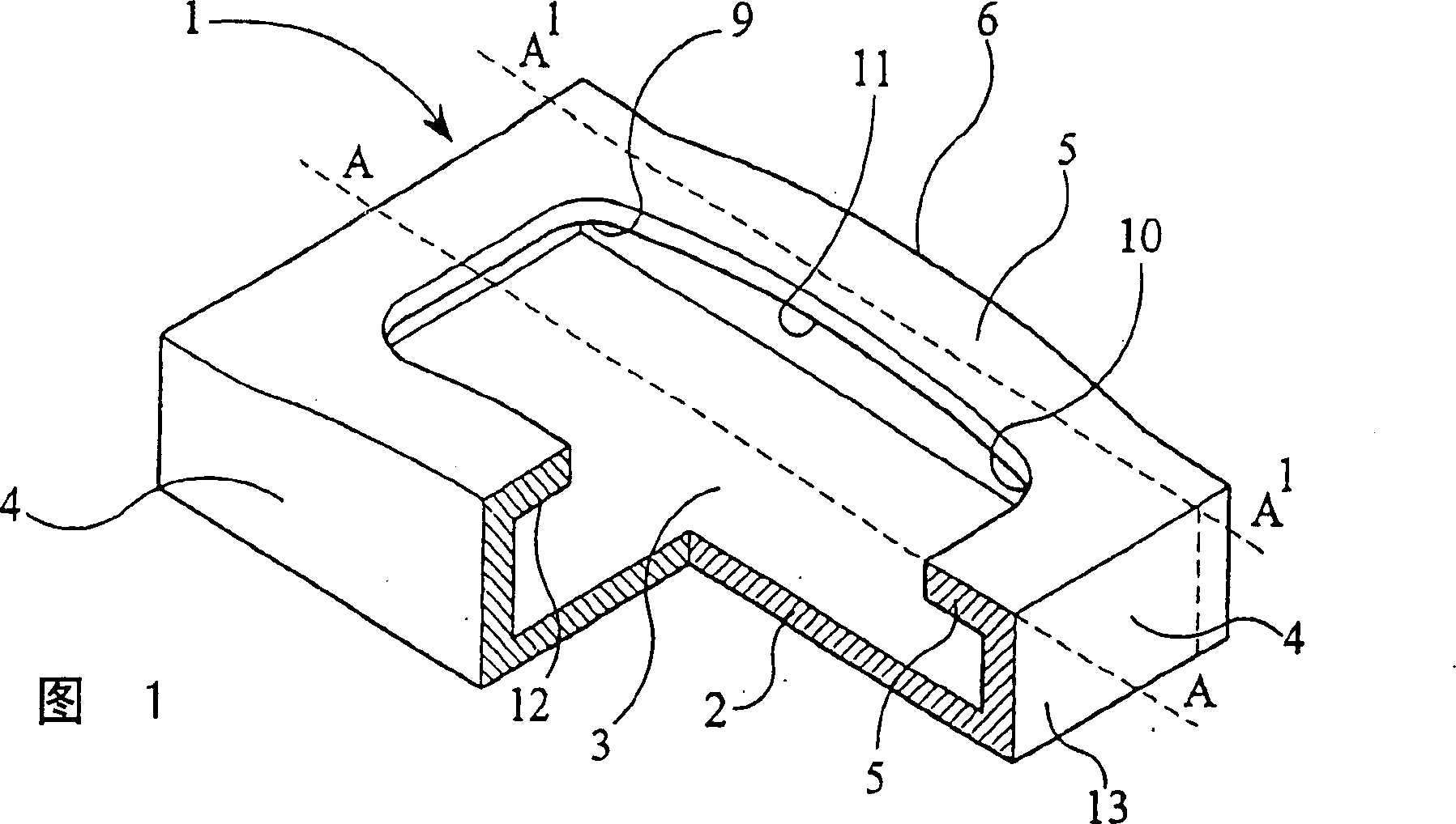
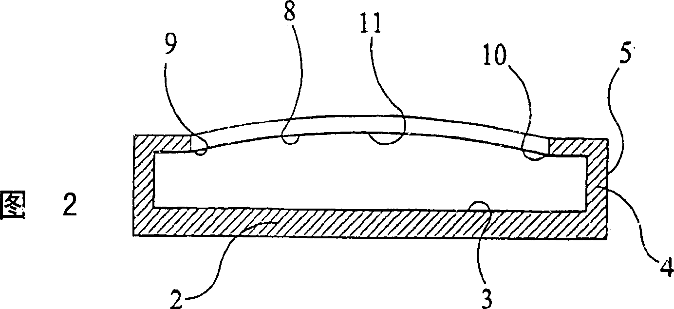
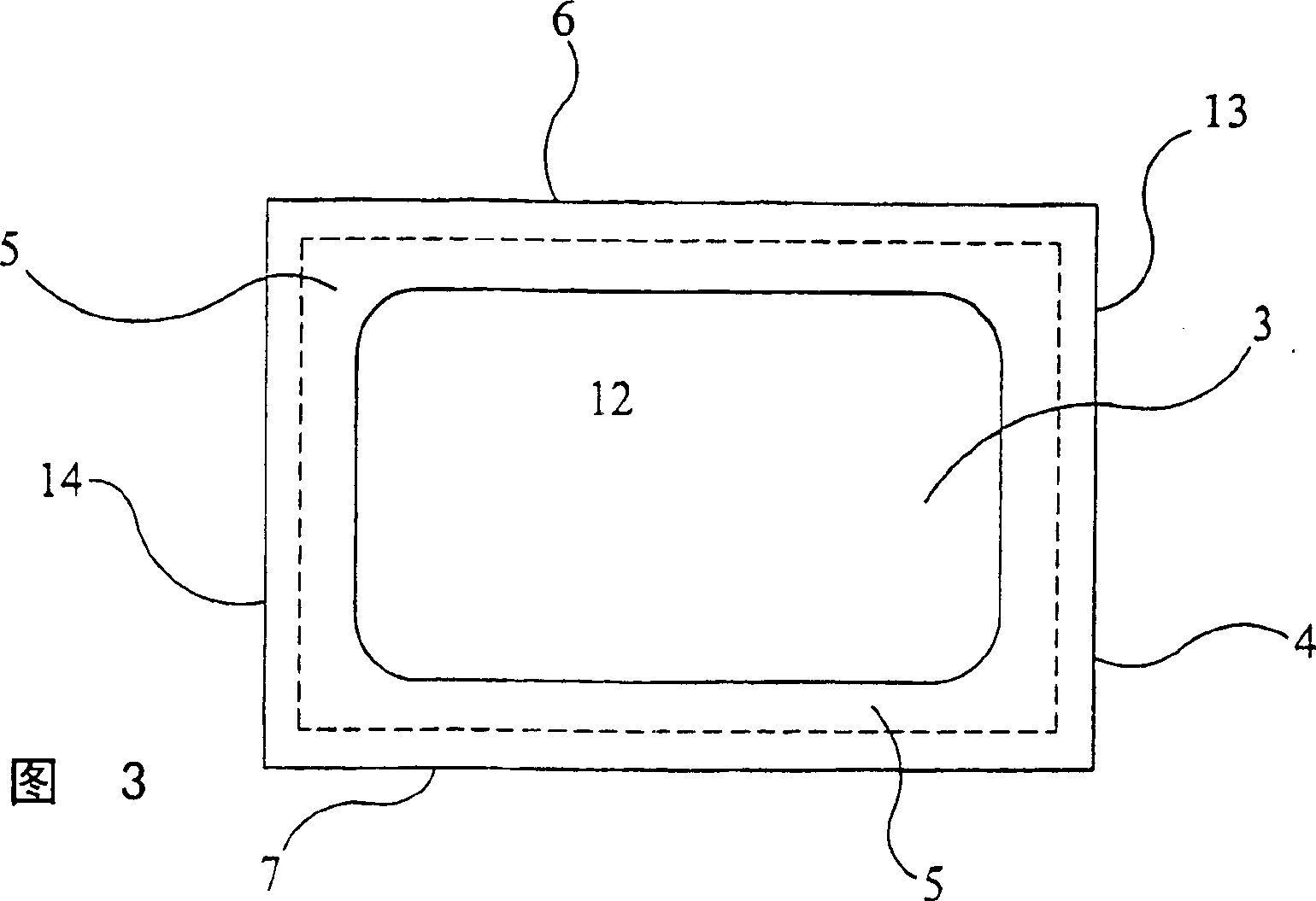
[0058] Figures 1 to 3 show an impact pad 1 comprising a base 2 having an impact surface 3, a wall 4 extending upwardly from the base 2 and an overhang 5 projecting inwardly from the wall 4 . Along the opposite parallel sides 6 and 7 of the impact pad, the lower surface 8 of the overhang 5 is arcuately curved. Referring to the side 6 of the impact pad 1, it can be seen that the vertical height of the overhang above the base plate increases gently, but not linearly, from a minimum at the end 9 to a maximum at the center 11 and back to The reference numeral 10 reduces again to a minimum value. Thus, the overhang forms an arched top over the perimeter of the floor. Side 7 has a similar arched portion 12 which is a mirror image of its symmetry on side 6 . The overhang portion 5 protruding from the opposite ends 13 , 14 of the impact pad has a generally uniform height above the base plate, ie the lower surface of the overhang is generally horizontal and parallel to the plane of th...


PUM


Abstract

A tundish impact pad (1,20,40,60) formed from refractory material comprising a base (1,22,42,62 having an impact surface which, in use, faces upwardly against a stream of molten metal entering a tundish, a wall (4,23,43,63) extending upwardly from the base around at least a part of the periphery of the impact surface, one or more portions of the upper part of the wall supporting one or more overhangs (5,24,44,64) which project inwardly over the periphery of the base. At least one of said overhangs has at least a part whose under-surface curves or slopes, the curvature or slope lying in a direction along the length of the wall. Preferably the pad has rectangular base and a pair of opposite walls is provided with an overhang that arches upwardly towards the centre of the wall. An overhang (33,34) on the second pair of walls can be, for example, planar and parallel to the base. The width of the curved or sloping overhangs increases in both directions away from its centre / top.

Description

technical field [0001] The present invention relates to a component of refractory material known in the technical field as an "impact pad" for processing molten metal, especially steel. In particular, the invention relates to impact pads placed within the tundish for attenuating turbulence in the flow of molten steel entering the tundish. The invention is particularly useful in continuous casting of steel. Background technique [0002] In the industrial production process of continuous steel casting, the tundish is used as a container for holding the above-mentioned molten metal, especially molten steel. In the continuous casting of steel, the molten steel fed to the tundish is generally high-grade steel that has gone through several production steps to make it suitable for a specific pour. These steps generally include, for example, one or more steps aimed at controlling the content of various elements present in the steel, such as carbon and other alloying constituents, ...

Claims


Application Information

Patent Timeline
Patent Type & Authority Patents(China)
IPC IPC(8): B22D41/00B22D11/10
CPCB22D41/003B22D41/00
Inventor D·R·扎查里亚斯J·莫里斯E·沃特施
Owner FOSECO INT LTD
Learn More