Heat exchanger

A heat exchanger and fin technology, applied in the field of heat exchangers with improved heat exchange function, can solve problems such as hindering the flow of air in the fins 102, increasing the size of the heat exchanger, and reducing the heat exchange function.

Inactive Publication Date: 2007-03-28
LG ELECTRONICS INC
View PDF2 Cites 0 Cited by
  • Summary
  • Abstract
  • Description
  • Claims
  • Application Information

AI Technical Summary

Problems solved by technology

[0009] However, according to the conventional heat exchanger described above, condensed water generated during the heat exchange operation may remain on the surface of the fins 102 by means of surface tension, thereby hindering the flow of air between the fins 102, and the gap between the air and the fluid Reduced heat exchange between
[0010] Also, the distance between the fins 102 should be kept larger than a certain degree to prevent condensed water from remaining in the space between the fins 102 through which air passes, thus increasing the size of the heat exchanger

Method used


Image

  • Heat exchanger
  • Heat exchanger
  • Heat exchanger

Examples


Embodiment Construction

[0026] Preferred embodiments of the invention will now be described in detail, examples of which are illustrated in the accompanying drawings.

[0027] There are a number of embodiments of the heat exchanger according to the invention, the most preferred embodiments being described below.

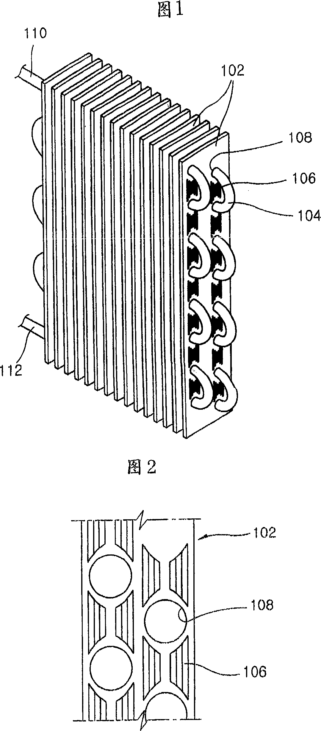
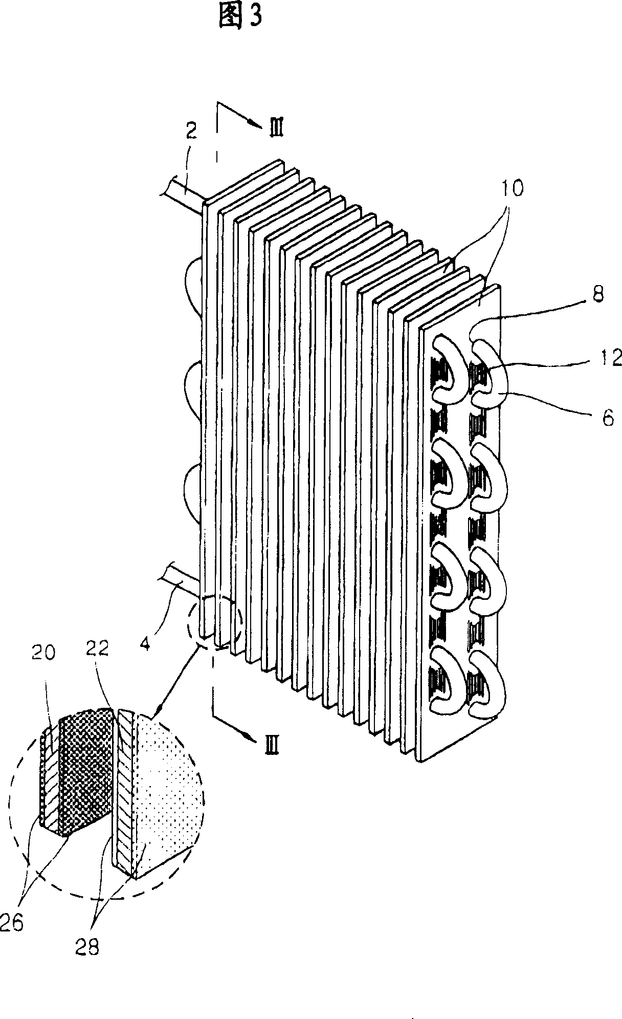
[0028] Figure 3 is a perspective view of a heat exchanger according to the present invention.

[0029] The heat exchanger according to the invention comprises: a tube 6, through which the fluid flows, which is meandering, connected on one side to the inlet tube 2 into which the fluid flows, and on the other side to the outlet tube 4, the fluid which completes the heat exchange It is discharged through the outlet pipe 4; a plurality of fins 10 are arranged with a certain gap between them, and a plurality of through holes 8 are included to allow the tube 6 to pass through, thereby enlarging the area in contact with the air.

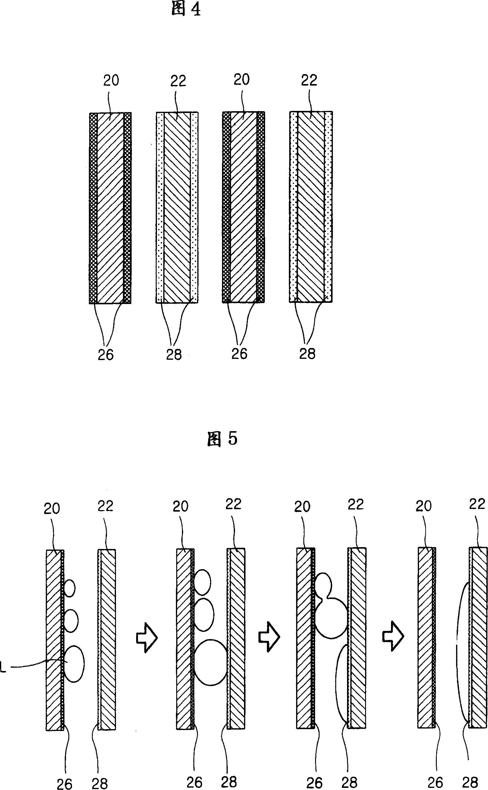
[0030] The fin 10 is made in a plate shape with a certain length a...


PUM


Abstract

A heat exchanger, which is able to improve heat transmission function and reduce distances between fins to improve heat exchanging function and reduce a size by coating surfaces of the fins with certain materials to make condensate water attached on the surfaces of the fins discharged smoothly, comprises fins arranged with certain gaps therebetween to flow the air; and a tube, through which the fluid passes, installed to penetrate the fins, and the fins are arranged so that one surfaces treated by hydrophilic material and the other surfaces treated by water repellent material face each other with certain gaps therebetween.

Description

technical field [0001] The present invention relates to a heat exchanger, and more particularly to a heat exchanger capable of improving the heat exchanging function by smoothly discharging condensed water generated during heat exchanging operation. Background technique [0002] Generally, a heat exchanger is a device that exchanges heat by bringing two different fluids into direct or indirect contact with each other, and it is mainly used in heaters, coolers, evaporators or condensers. [0003] FIG. 1 is a perspective view of a finned tube type heat exchanger used in a refrigeration device according to the conventional art, and FIG. 2 is a plan view of fins in the heat exchanger according to the conventional art. [0004] A conventional heat exchanger includes a plurality of fins 102 arranged with a gap therebetween, and tubes 104 through which a fluid flows, which are fitted through the fins 102 . [0005] The fins 102 are plate-type fins each having a predetermined lengt...

Claims


Application Information

Patent Timeline
Patent Type & Authority Patents(China)
IPC IPC(8): F28F17/00F28F19/02F25B39/02F28D1/047F28F1/32F28F13/04F28F13/18
CPCF28D1/0477F28F2245/04F28F1/325F28F13/04F28F2245/02F28F17/00
Inventor 高喆洙吴世允吴世基史容澈张东延
Owner LG ELECTRONICS INC
Why Eureka
Try Eureka