Illumination opitcal system and projector
A lighting optical system and optical element technology, applied in the field of projectors, can solve problems such as difficult to realize, high price, and changing spectral characteristics
- Summary
- Abstract
- Description
- Claims
- Application Information
AI Technical Summary
Problems solved by technology
Method used
Image

Examples
Embodiment approach 1
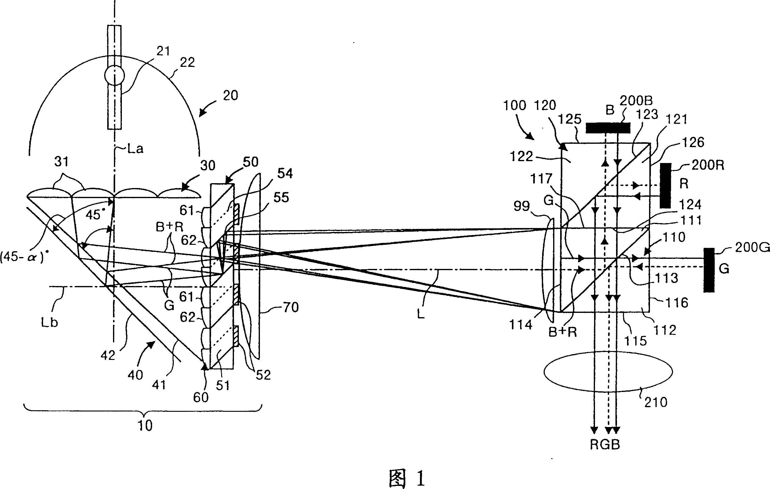
[0056] FIG. 1 shows an embodiment of a projector comprising the illumination optical system of the present invention. This projector has: an illumination optical system 10 ; a color separation and synthesis optical system 100 ; three reflective liquid crystal panels 200R, 200G, and 200B as light modulators; and a projection lens 210 .
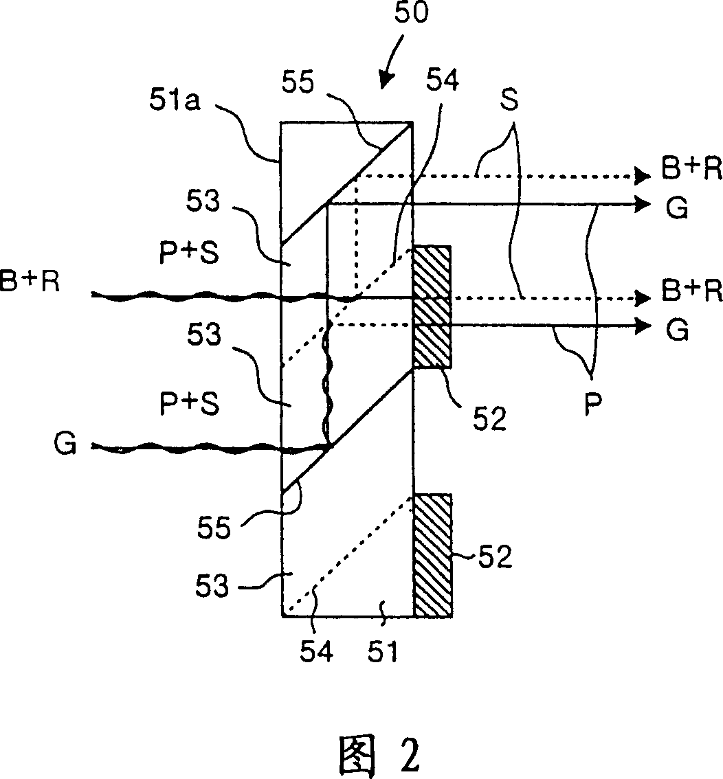
[0057] The illumination optical system 10 has: a light source 20 emitting substantially parallel light beams; a first lens array 30 constituting a beam splitting optical element; a color light separation optical element 40; a polarization conversion element 50; a second lens array 60 constituting a transmission optical element; The superimposed lens 70 as a superimposed optical element has a function of generating illumination light beams having substantially the same polarization direction for each color light.
[0058] The light source 20 has a light source lamp 21 and a concave mirror 22 . The light emitted from the light source lamp 21 is ...
Embodiment approach 2
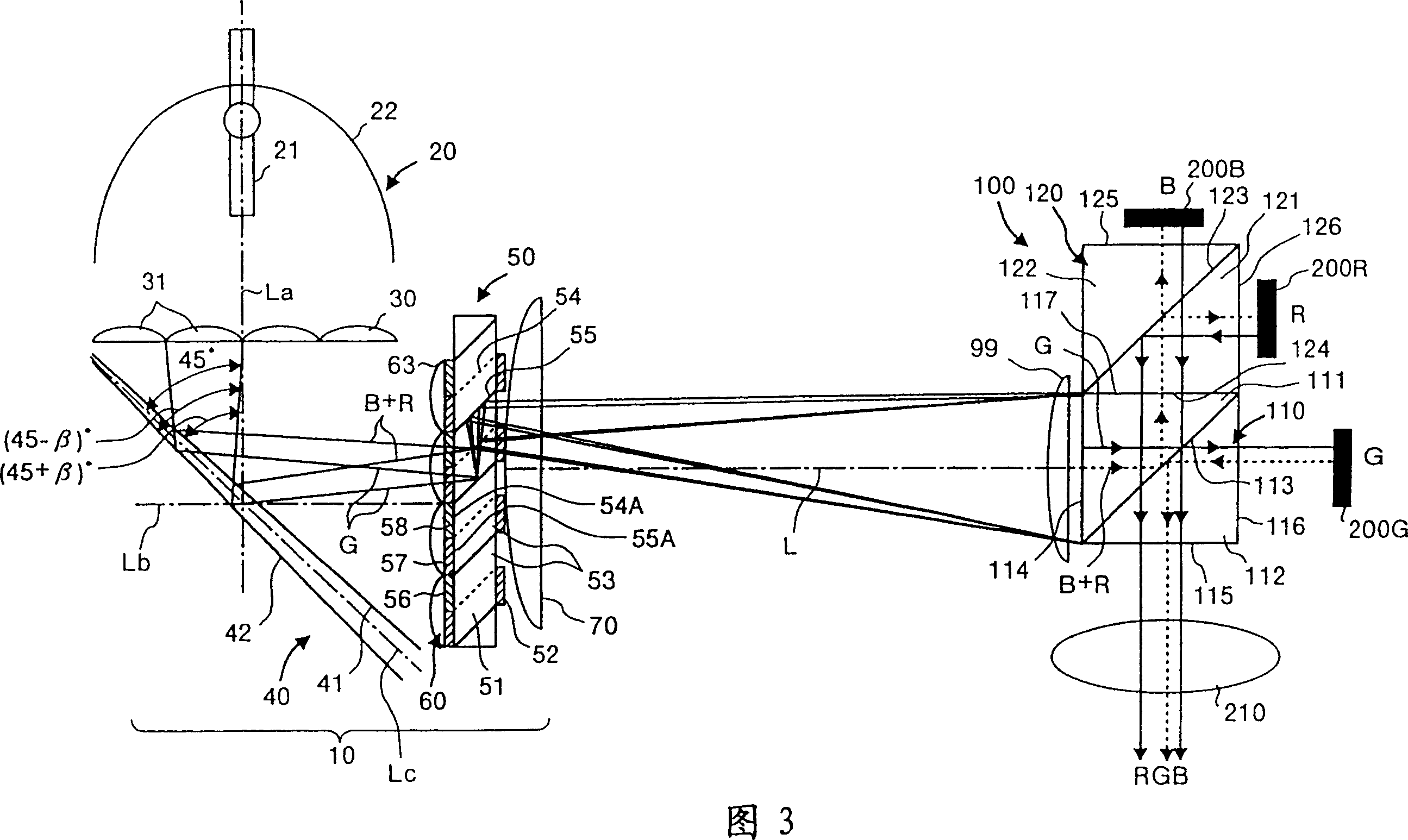
[0087] Fig. 3 shows another embodiment of a projector comprising the illumination optical system of the present invention. This embodiment differs from the first embodiment described above in the arrangement of the mirrors 41 and 42 of the color light separation optical element 40 and the provision of the color separation filter array 56 . About other structure, it is the same as Embodiment 1. In addition, in each embodiment described later including this embodiment, the same reference numerals as those attached to Fig. 1 and Fig. 2 are assigned to the same constituent elements as those already described, and the symbols are omitted. illustrate. In addition, in the color separation / synthesis optical system 100 of FIG. 3 , light rays drawn with solid lines indicate P-polarized light, and light rays drawn with dotted lines indicate S-polarized light.
[0088] In this embodiment, the dichroic mirror 41 and the reflecting mirror 42 of the color light separation optical element 4...
Embodiment approach 3
[0093] Figure 4 shows another embodiment of a projector comprising the illumination optical system of the present invention. This embodiment differs from the second embodiment described above mainly in the arrangement of the mirrors 41 and 42 of the color light separation optical element 40 and the structure of the second lens array 60 . About other structure, it is the same as Embodiment 2. In the color separation / synthesis optical system 100 in FIG. 4, the light rays drawn by solid lines indicate P-polarized light, and the light rays drawn by dotted lines indicate S-polarized light.
[0094] In the present embodiment, the dichroic mirror 41 and the reflective mirror 42 of the color light separation optical element 40 are parallel to each other and arranged at a predetermined distance t along the direction of the optical axis La. Here, the predetermined amount t is substantially equal to the interval in the direction along the incident end face 51 a of the polarization split...
PUM
 Abstract
Description
Claims
Application Information
 - R&D
- Intellectual Property
- Life Sciences
- Materials
- Tech Scout
- Unparalleled Data Quality
- Higher Quality Content
- 60% Fewer Hallucinations
Browse by: Latest US Patents, China's latest patents, Technical Efficacy Thesaurus, Application Domain, Technology Topic, Popular Technical Reports.
© 2025 PatSnap. All rights reserved.Legal|Privacy policy|Modern Slavery Act Transparency Statement|Sitemap|About US| Contact US: help@patsnap.com