
Glass bonded fiber array and method for the fabrication thereof

A fiber and glass technology, used in bundles of optical fibers, instruments, optical components, etc., can solve problems such as damage to the connection between optical fibers and supporting elements, unacceptable long processing time, and cracking of bonding materials.

Inactive Publication Date: 2007-05-30
SAMSUNG ELECTRONICS CO LTD
View PDF9 Cites 0 Cited by
  • Summary
  • Abstract
  • Description
  • Claims
  • Application Information

AI Technical Summary

Problems solved by technology

In addition, some commonly used bonding materials can absorb moisture, which can significantly reduce the ability of the bonding material to firmly fasten the fibers to each other and to the support element
Absorption of moisture can also tend to cause the bonding material to swell, which can lead to dimensional changes in the bonding material, which can damage the connection between the optical fiber and the support element
For example, dimensional changes from the bonding material can lead to movement or even detachment of the optical fiber from the support element
In addition, long-term exposure to other environmental conditions such as heat, oxidation, and photosensitive degradation can lead to cracking of the bonding material over the period of said exposure
Another disadvantage associated with the use of certain bonding materials is the unacceptable requirement of very long processing times, often at elevated temperatures, which can hinder mass production

Method used


Image

  • Glass bonded fiber array and method for the fabrication thereof
  • Glass bonded fiber array and method for the fabrication thereof
  • Glass bonded fiber array and method for the fabrication thereof

Examples


Embodiment Construction

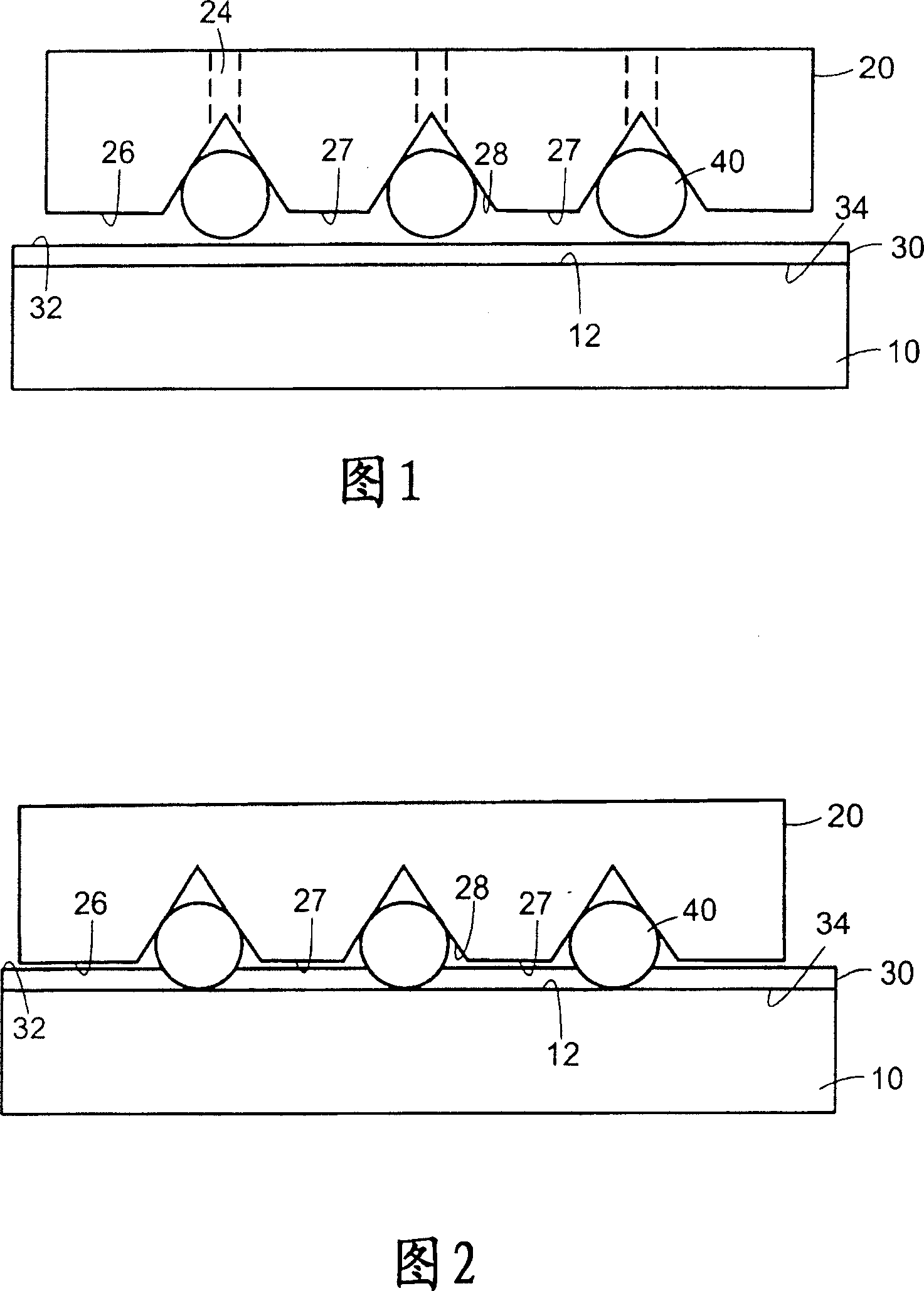
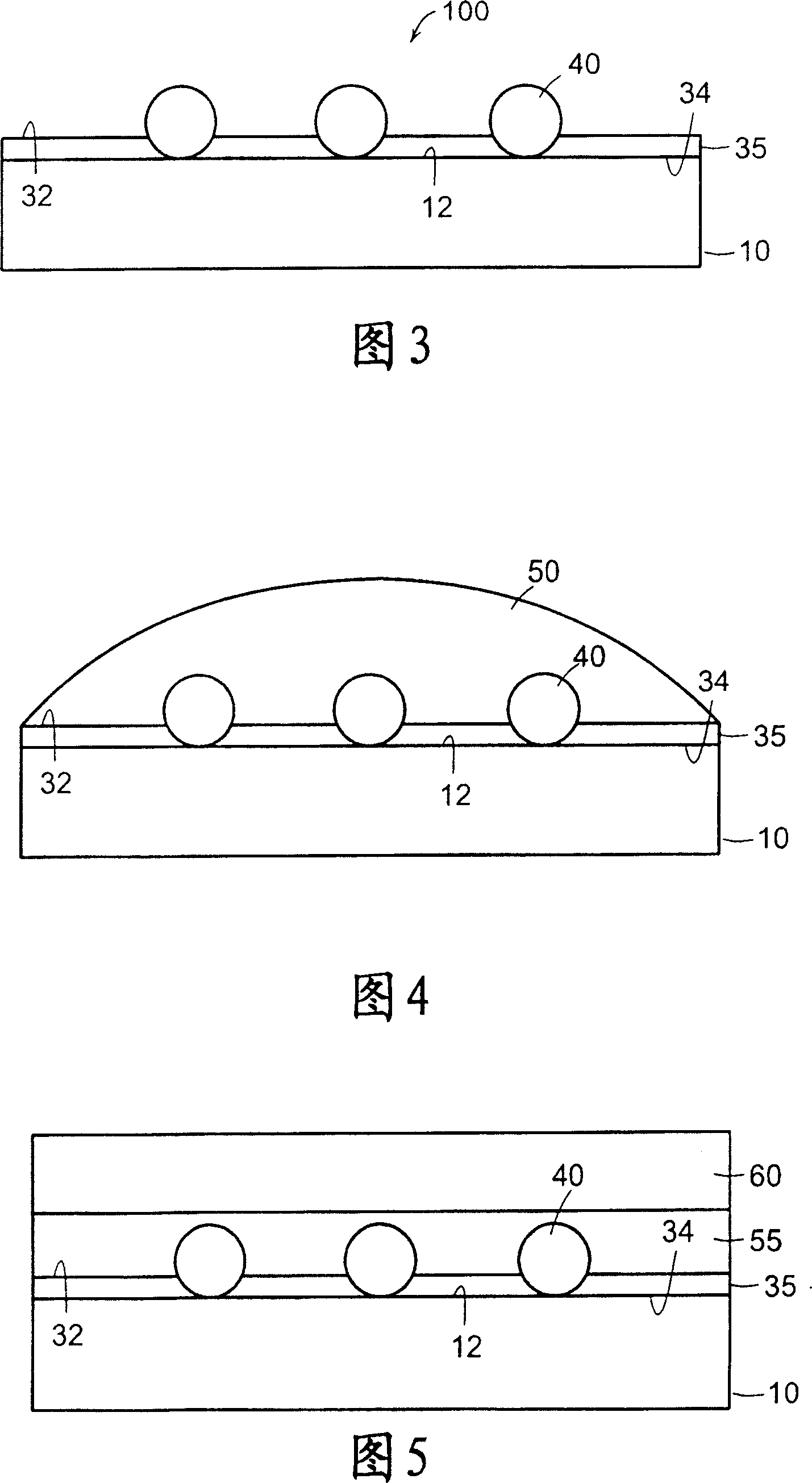
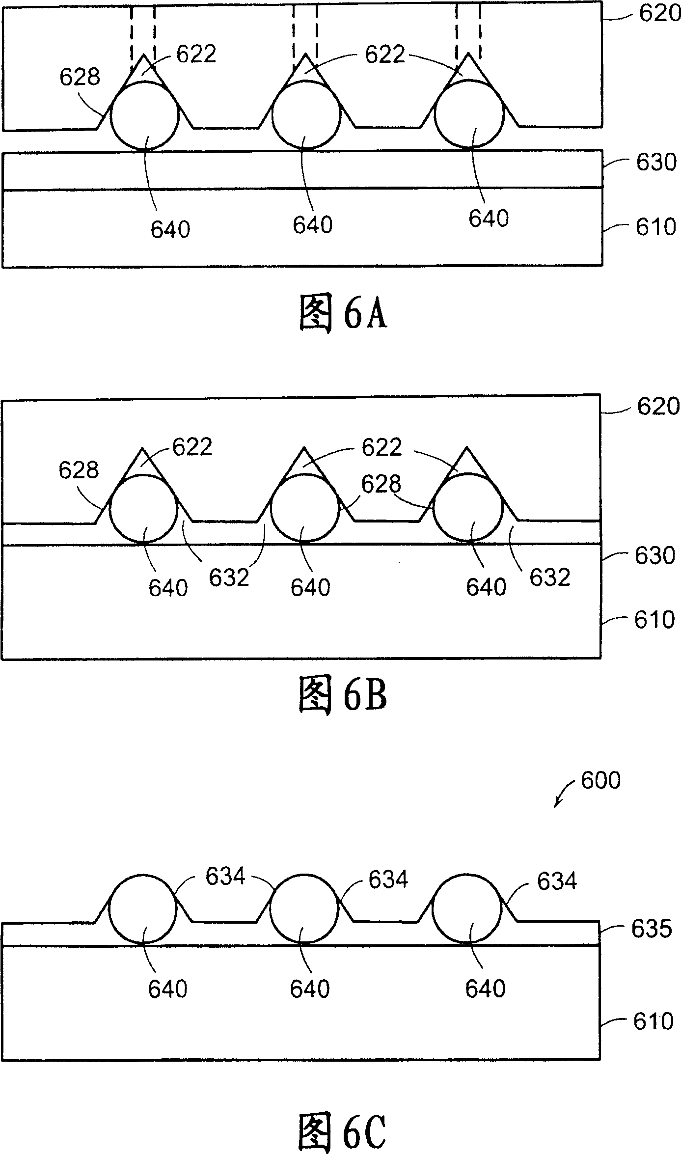
[0027] The present invention relates to precise installation between an optical fiber and a supporting element so that the fiber core relative to the selected position of the supporting element is safely and permanently connected to the supporting element at a precisely designated position, thereby providing an optical fiber bundle. Providing precise placement of the fiber core relative to the support element is critical to the ability of the fiber core to align with other optical elements when the fiber bundle is used in combination with other system components. Generally, an optical fiber has a central optical core surrounded by a cladding, which is covered by a buffer and a jacket. The precise placement of the fiber core relative to the support element is provided by aligning the buffer-free, unjacketed optical fiber portion with respect to the reference surface of the support element. A vitreous bonding material (such as welding glass) is used to fix the precisely arranged fib...


PUM

PropertyMeasurementUnit
melting pointaaaaaaaaaa
glass transition temperatureaaaaaaaaaa

Abstract

In accordance with the present invention a fiber optic array is provided. The array includes a substrate having a fiber support surface. The array further includes an optical fiber having a fiber portion that includes an un-jacketed, un-buffered optical core segment. The un-jacketed, un-buffered optical core segment is placed in contact with the fiber support surface to orient the optical core segment at a selected position relative to the support surface. In addition, the array includes a solder glass chemically bonded to the optical core segment and the fiber support surface so that the optical core segment is secured at a predetermined location relative to the support surface of the substrate. A method for fabricating such a fiber optic array is also provided.

Description

Technical field [0001] The present invention generally relates to fiber optic bundles, and more specifically, the present invention relates to a fiber optic bundle having a buffer-free, non-jacketed optical fiber fastened to a support member with welding glass. Background technique [0002] In applications ranging from digital communications to optical computing, the use of multiple optical channels (such as optical fibers) has become quite common with increasing system bandwidth requirements. At the same time, miniaturization is still an important goal in these applications. High fiber packing density helps to achieve miniaturization and increase space bandwidth products. In addition, since the fiber core must be accurately aligned with other devices or fibers of the system, the precise positioning of the fiber core is a key goal in obtaining acceptable system performance. Fiber bundles provide an ideal method for handling multiple optical fibers while striving to achieve miniat...

Claims


Application Information

Patent Timeline
Patent Type & Authority Patents(China)
IPC IPC(8): G02B6/12G02B6/40C03C27/06G02B6/00G02B6/08G02B6/36G02B6/38G02B6/42
CPCC03C27/06G02B6/362G02B6/3636G02B6/08G02B6/3855C03C8/245G02B6/4238C03C25/107G02B6/3652C03C25/1061
Inventor 马丁·G·梅德尔威廉·斯泰西明道加斯·F·道塔塔斯丹·A·斯坦伯格
Owner SAMSUNG ELECTRONICS CO LTD
Features
  • Generate Ideas
  • Intellectual Property
  • Life Sciences
  • Materials
  • Tech Scout
  • Unparalleled Data Quality
  • Higher Quality Content
  • 60% Fewer Hallucinations
Learn More