Network type monitoring device

A monitoring device and network technology, applied in the field of alarm information, can solve the problems of inaccurate change control, high cost, and difficulty in obtaining alarm images.

Inactive Publication Date: 2007-05-30
PANASONIC CORP
View PDF5 Cites 0 Cited by
  • Summary
  • Abstract
  • Description
  • Claims
  • Application Information

AI Technical Summary

Problems solved by technology

[0007] The first problem is that the network distribution of images from safety devices such as cameras and switches, the registration records of alarm information from sensors and the above-mentioned safety devices, and the distribution of the above-mentioned alarm information are realized by different devices. difficult to build relationships
[0008] The second problem is that if an image coding and storage device corresponding to the number of image input channels from cameras and image output devices connected to the network-type monitoring device is provided, the number of parts will be large and the cost will be high.
[0009] The third problem is that in order to cope with various reproduction terminals such as portable terminals such as PCs, mobile phones, and PDAs (Personal Digital Assistants), and information appliances such as TVs, it is necessary to efficiently display different displays for each terminal. Ability and display format correspondence
[0010] The fourth problem is that it is impossible to display the images of multiple channels on the same terminal at the same time by using the image encoding device and the image storage device of one system that can only process one channel by simply switching the image input channel.
[0011] The 5th problem is because only the latest image is stored in the existing coded image storage method, it is difficult to obtain the alarm image before the alarm occurs
[0012] The sixth question is when the second alarm occurs during the storage of the first series of alarm images. Depending on the application, the first alarm image or the second alarm image is required.
[0013] The seventh problem is that there must be special special software for viewing alarm information and obtaining and displaying alarm images
[0018] The twelfth problem is that due to the transmission delay of the network, when controlling a monitoring device with a simple control command, it takes time from the start of a series of operations to the end of the operation, or the accuracy expected by the operator of the monitoring device cannot be achieved. to control the amount of change

Method used


Image

  • Network type monitoring device
  • Network type monitoring device
  • Network type monitoring device

Examples


Embodiment 1

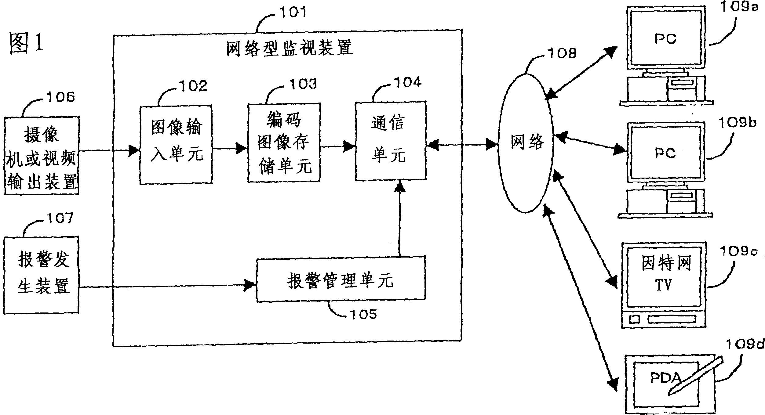
[0129] 1 is a block diagram showing the structure of the first embodiment of the network monitoring device of the present invention. The network monitoring device 101 includes an image input from image information output from an image output device 106 such as a camera or a switch. The input unit 102, the coded image storage unit 103 that encodes and stores the image information obtained by the image input unit 102, detects whether the alarm generating device 107 has an alarm and stores the alarm management unit 105, and connects the regeneration terminal 109a through the network 108 to 109d sends the coded image stored in the coded image storage unit 103 or the alarm information stored in the alarm management unit 105 to the communication unit 104 of the reproduction terminal 109a to 109d via the network 108 according to the request from the reproduction terminal 109a to 109d .

[0130] The reproduction terminals 109a to 109d communicate with the network monitoring device 101 and...

Embodiment 2

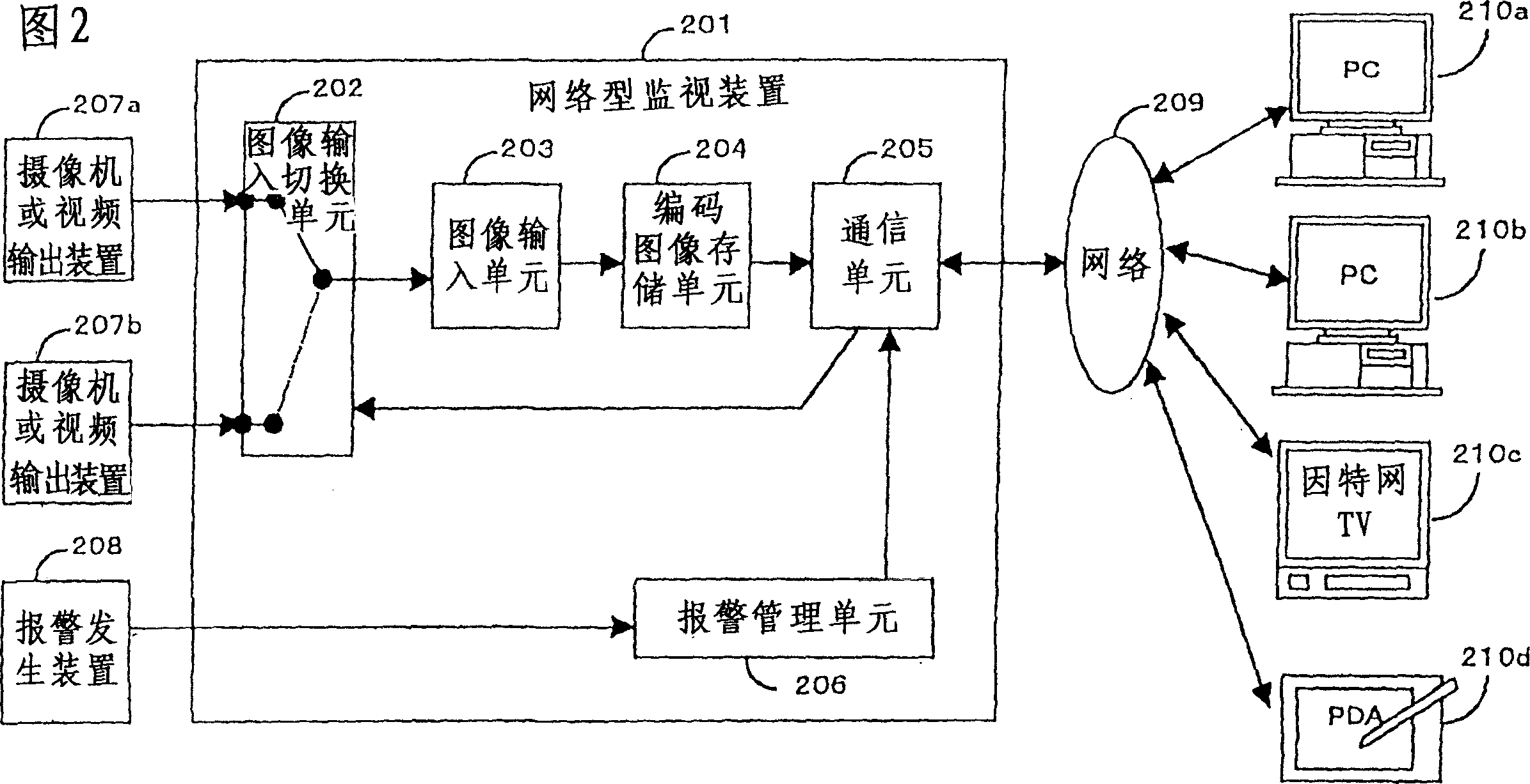
[0138] 2 is a block diagram showing the structure of the second embodiment of the network-type surveillance device of the present invention. In addition to the structure of the first embodiment, it also includes a pair of image output devices 207a to 207b such as multiple cameras or video output devices. Connected to the image input switching unit 202 for switching, the image input unit 203 that inputs the image information output from the channel selected by the image input switching unit 202 in the image output devices 207a to 207b, and the same transmission code as in the first embodiment In addition to the image and alarm information, the communication unit 205 receives an image input channel switching request from the reproduction terminals 210a to 210d via the network 209, and instructs the image input switching unit 202 to perform channel switching.

[0139] The communication unit 205 is connected to the network 209, receives channel switching requests sent by the reproduct...

Embodiment 3

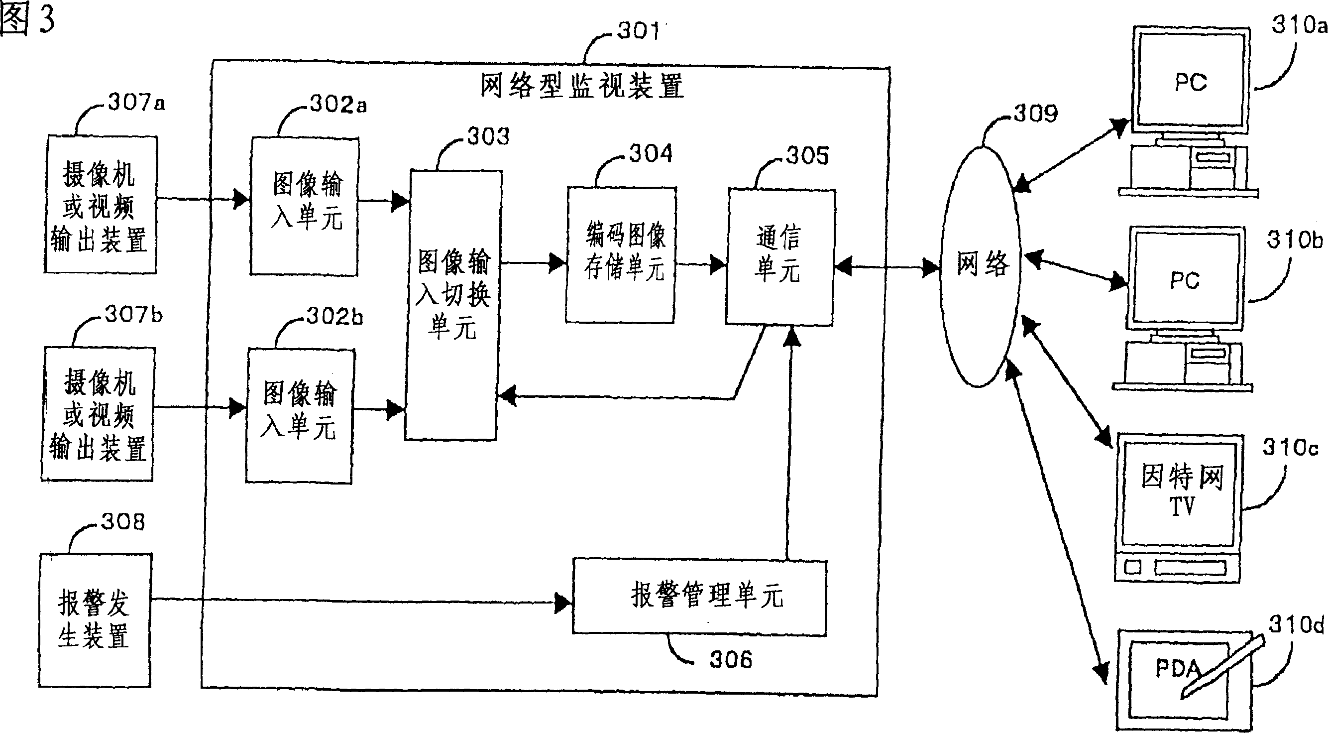
[0145] 3 is a block diagram showing the structure of the third embodiment of the network monitoring device of the present invention. In addition to the structure of the first embodiment, it also includes the connection with the image output devices 307a to 307b and the slave image output devices 307a to 307b. The image input units 302a to 302b that input the output image information, the image input switching unit 303 that switches the connection with the plurality of image input units 302a to 302b and the coded image storage unit 304, and the same as the first embodiment except that the code is transmitted In addition to the image and alarm information, the communication unit 305 that receives the image input channel switching request from the reproduction terminals 310a to 310d via the network 309, and instructs the image input switching unit 303 to perform channel switching.

[0146] The communication unit 305 is connected to the network 309, receives the channel switching requ...


PUM


Abstract

To provide a networking monitor device where a reproduction terminal can acquire a picture from alarm information from a unit in a monitor area via a network. The networking monitor device consists of a picture input section that receives picture information received from a picture output device such as a camera or a switcher, a coded picture storage section that encodes picture information and stores the coded information, an alarm management section that detects presence of occurrence of an alarm from an alarm generator to store alarm information, and a communication section that receives a request from a reproduction terminal via a network transmits the coded picture stored in the coded picture storage section or the alarm information stored in the alarm amplifier section upon the request therefrom.

Description

Technical field [0001] The present invention relates to techniques that perform image transfer through a network, and more particularly to techniques for monitoring an image of an image of an image of a monitoring machine by a terminal such as a remote computer and an alarm information such as a sensor. Background technique [0002] The configuration of the prior art monitoring system includes monitoring the camera, the switch, the monitor image machine, the image display, and the coaxial cable connected to the above various machines and the control information, the monitoring person must have been Monitor the above-described monitoring of the fixed location of the security room. In addition, the transmission of the alarm information is a system-dedicated line that is separated from the coaxial cable for transmitting images. [0003] In addition, existing network-type image transmitting devices are implemented on PC loading dedicated software on PC connecting a PC (Personal Compu...

Claims


Application Information

Patent Timeline
Patent Type & Authority Patents(China)
IPC IPC(8): H04N7/18G08B13/196G06F13/00
CPCG08B13/19656G08B13/19669G08B13/19676G08B13/19645H04N7/181
Inventor 东村守中村学滨田准一三泽基宏
Owner PANASONIC CORP
Why Eureka
Try Eureka