Energy displacement ventilating system and spiral energy displacement device

A displacement ventilation and spiral technology, applied in the field of ventilation systems, can solve the problems of easy fatigue, energy waste, high energy consumption, etc., and achieve the effect of strengthening circulation, reducing energy consumption, and reducing the harassment of outdoor noise

Inactive Publication Date: 2007-06-06
何京生
View PDF6 Cites 0 Cited by
  • Summary
  • Abstract
  • Description
  • Claims
  • Application Information

AI Technical Summary

Problems solved by technology

[0002] Air is one of the basic elements of human existence. The quality of air has directly affected people’s daily life. Air with insufficient cleanliness and insufficient oxygen will directly lead to problems in our body functions, such as decreased resistance, fatigue, etc. , thus causing various diseases. Therefore, ventilation systems are equipped in office buildings, hotels, restaurants, swimming pools, gymnasiums, assembly halls, dance halls, gyms, factory workshops, canteens, bathhouses, shops, cinemas and other places. Traditional Ventilation and ventilation systems (as shown in Figure 1) mostly include an air supply unit 41 and an exhaust unit 42. The air supply unit 41 imports the outdoor air into the room after heating or cooling, and the exhaust unit 42 extracts the dirty air in the room. It is directly exhausted to the outside, thereby forming a circulation system, constantly updating the air in the room, and keeping it at a suitable temperature, while the simpler ventilation and ventilation system only includes exhaust unit 42 (as shown in Figure 2), these ventilation There is a troublesome problem in the ventilation system, that is, it consumes a lot of energy. During the operation of the system, due to the large temperature difference between indoor and outdoor, the dirty air in the room (hot air in winter and cold air in summer) is discharged outside at the same time. , a large amount of energy is also discharged, on the contrary, in order to make the fresh air entering the room reach a suitable temperature, it needs to be additionally heated or cooled, such that one in and one out will cause a lot of energy waste

Method used


Image

  • Energy displacement ventilating system and spiral energy displacement device
  • Energy displacement ventilating system and spiral energy displacement device
  • Energy displacement ventilating system and spiral energy displacement device

Examples


Embodiment Construction

[0028] The invention will be described in further detail below in conjunction with the accompanying drawings.

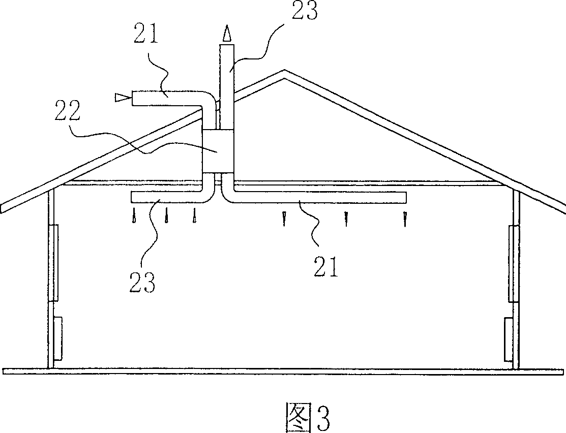
[0029] As shown in Figure 3, the energy displacement ventilation system of the present invention is mainly made up of air inlet pipe 21, air exhaust pipe 23 and spiral energy displacer 22, and air inlet pipe 21 and exhaust air pipe 23 are connected with the spiral energy displacer 22 respectively. The air inlet is communicated with the air outlet, and electric fans are respectively installed on the air inlet pipe 21 and the air exhaust pipe 23 to drive the air circulation to take a breath.

[0030] As shown in Figure 4 and Figure 5, the spiral energy displacer 22 is mainly composed of a cylindrical shell 2 and a double vortex inner core 4, the double vortex inner core 4 is separated by two thin plates 1 through the isolation medium 3 and rolled into a double vortex The two-layer thin plate 1 is rolled into a vortex-shaped cylinder and fixed by a solid barrel-shaped s...


PUM


Abstract

The energy displacing ventilation system includes air inlet pipeline, air outlet pipeline, and spiral energy displacer with air inlet and air outlet connected separately with the air inlet pipeline and the air outlet pipeline. On each of the air inlet pipeline and the air outlet pipeline, there is circulating driver. The spiral energy displacer includes cylindrical casing and double helical inner core, and the double helical inner core is divided with one diameter into two, one upper and one lower, semi-circular parts to form one semi-circular inlet and one semi-circular outlet. The present invention can convert the energy of exhausted gas to input air so as to reduce the power consumption for heating or cooling fresh air and has obvious energy saving effect.

Description

technical field [0001] The invention relates to a ventilation system, in particular to an energy replacement ventilation system and a spiral energy displacer in which the stale air can convert its own energy to incoming fresh air during the discharge process. Background technique [0002] Air is one of the basic elements of human existence. The quality of air has directly affected people’s daily life. Air with insufficient cleanliness and insufficient oxygen will directly lead to problems in our body functions, such as decreased resistance, fatigue, etc. , thus causing various diseases. Therefore, ventilation systems are equipped in office buildings, hotels, restaurants, swimming pools, gymnasiums, assembly halls, dance halls, gyms, factory workshops, canteens, bathhouses, shops, cinemas and other places. Traditional Ventilation and ventilation systems (as shown in Figure 1) mostly include an air supply unit 41 and an exhaust unit 42. The air supply unit 41 imports the outdo...

Claims


Application Information

Patent Timeline
Patent Type & Authority Patents(China)
IPC IPC(8): F24F7/08F28D9/04
Inventor 何京生
Owner 何京生
Why Eureka
Try Eureka