Optical disk device

An optical disc device and optical disc technology, which are applied to optical recording heads, head configuration/installation, optical recording/reproduction, etc., can solve the problems of tracking error signal interference, tracking disturbance, deviation, etc., to suppress interference, reduce The effect of tracking bias

Inactive Publication Date: 2007-06-06
PANASONIC CORP
View PDF8 Cites 0 Cited by
  • Summary
  • Abstract
  • Description
  • Claims
  • Application Information

AI Technical Summary

Problems solved by technology

[0003] However, when there is a scratch on the surface of the optical disc, foreign matter is attached, or the recorded pit is damaged (this situation is called a defect), when the light beam enters the defective part, the defect will cause a large impact on the tracking error. Signal interference causes the tracking of the beam to change. When the beam leaves the defect part, the tracking will be disturbed or deviated

Method used


Image

  • Optical disk device
  • Optical disk device
  • Optical disk device

Examples


no. 1 Embodiment approach

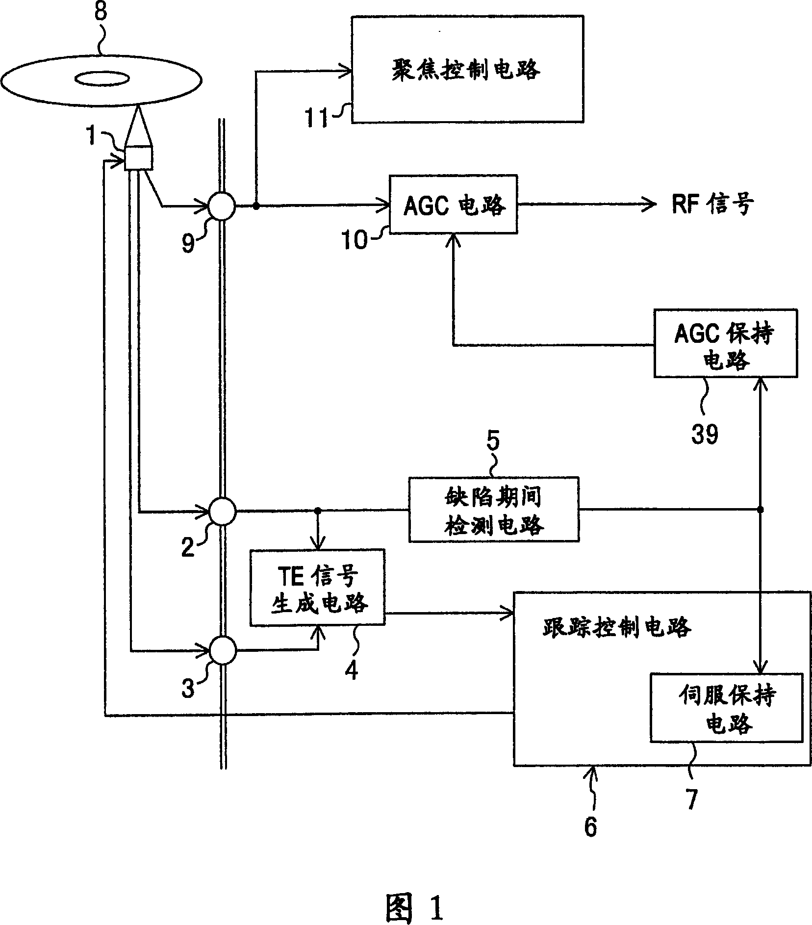
[0062] FIG. 1 shows an optical disc device according to a first embodiment of the present invention.

[0063] In the optical disc device shown in Fig. 1, 1 is an optical pickup, 8 is an optical disc, 2 is a first output terminal for obtaining the return light of the preceding sub-beam, 3 is for obtaining the second output terminal for the return light of the subsequent sub-beam, and 9 is for obtaining the main output terminal. The third output terminal of the beam return light, 4 is a TE signal generating circuit (tracking error signal generating device), 6 is a tracking control circuit (tracking control device), 7 is a servo holding circuit (holding device), 10 is an AGC circuit (AGC device), 11 is a focus control circuit (focus control device), and 39 is an AGC holding circuit (AGC holding device). The above configuration is the same as that of the optical disc device of FIG. 14 already described, and therefore its detailed description will be omitted.

[0064] As shown in ...

no. 2 Embodiment approach

[0077] FIG. 4 shows an optical disc device in a second embodiment of the present invention. The same reference numerals are assigned to the same parts as those in FIG. 1 , and description thereof will be omitted.

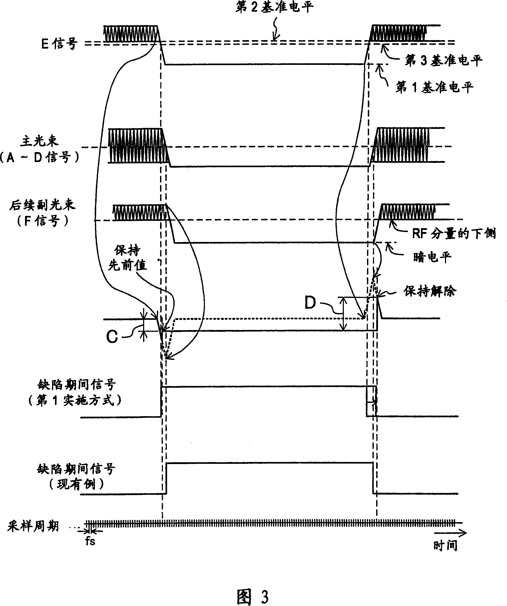
[0078] The difference between the optical disk device of this embodiment and the first embodiment shown in FIG. 1 is that not only the defect period detection circuit 5 is connected to the first output terminal 2 that outputs the E signal, but also to the second output terminal 2 that outputs the F signal. Terminal 3 connection. Thus, the defect period can be detected by using the E signal that enters the defect period earlier than the main beam and the F signal that exits the defect period later than the main beam, thereby suppressing the amplitude of the tracking error signal when the tracking servo is maintained. It is possible to accurately detect the drop-out from the defect period, so it is possible to provide an optical disc device with little disturbance to...

no. 3 Embodiment approach

[0094] Hereinafter, an optical disc device according to a third embodiment will be described. This embodiment shows a further embodiment of the defect period detection circuit.

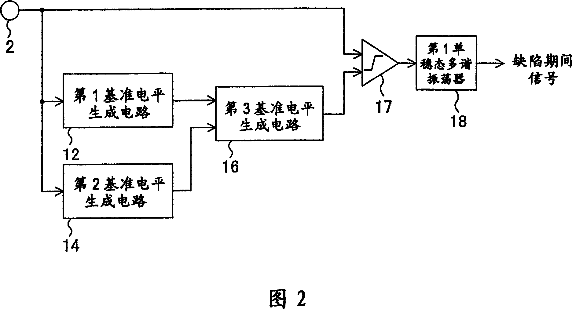
[0095] FIG. 7 shows the configuration of a defect period detection circuit in this embodiment (sixth technical means). The same reference numerals are assigned to the same parts as those in FIG. 5 , and description thereof will be omitted. The difference from Fig. 5 is that a peak hold circuit and a valley hold circuit are connected between the E signal and the F signal and the binarization circuit (pulse generation circuit), and between the outputs of the above peak hold circuit and the binarization circuit A drop rate variable circuit is connected between them.

[0096] Hereinafter, a detailed structure will be described. However, the configuration related to generation of the third and sixth reference levels is omitted since it is completely the same as in FIG. 5 .

[0097] The first pulse gene...


PUM


Abstract

In an optical disk device, an output terminal is connected to an optical pickup, and a preceding sub-beam returning light signal which is electrical signal obtained by converting returning light of a sub-beam preceding an main beam is output through the output terminal. A defect period detection circuit detects a defect period during which a beam is passing through a defective portion on an optical disk based on the preceding sub-beam returning light signal from the output terminal. A servo hold circuit holds tracking servo during the detected defect period. Therefore, even when an amplitude of an RF signal is quickly attenuated during the defect period, the defect period is detected at an early stage of the attenuation, thereby suppressing a change in an amplitude of a tracking error signal to a small level.

Description

technical field [0001] The present invention relates to a 3-beam type optical disc device for reproducing and outputting information recorded on an optical disc. Background technique [0002] Generally speaking, in an optical disc device that reproduces an optical disc such as a CD (Compact Disk) or a DVD (Digital Versatile Disk), it is used to make the read light spot of the light beam from the optical pickup follow the pit on the optical disc. Tracking control (tracking servo) of the track of the string is essential. This tracking servo is performed by generating a tracking error signal based on a signal of return light (reflected light) from the optical disc detected by the optical pickup, and based on the tracking error signal. [0003] However, when there is a scratch on the surface of the optical disc, foreign matter is attached, or the recorded pit is damaged (this situation is called a defect), when the light beam enters the defective part, the defect will cause a l...

Claims


Application Information

Patent Timeline
Patent Type & Authority Patents(China)
IPC IPC(8): G11B7/00G11B7/09G11B7/12G11B20/18
CPCG11B7/0948
Inventor 越田浩旨春井正德中田康夫坂善光金野耕寿片田真三康
Owner PANASONIC CORP
Why Eureka
Try Eureka