

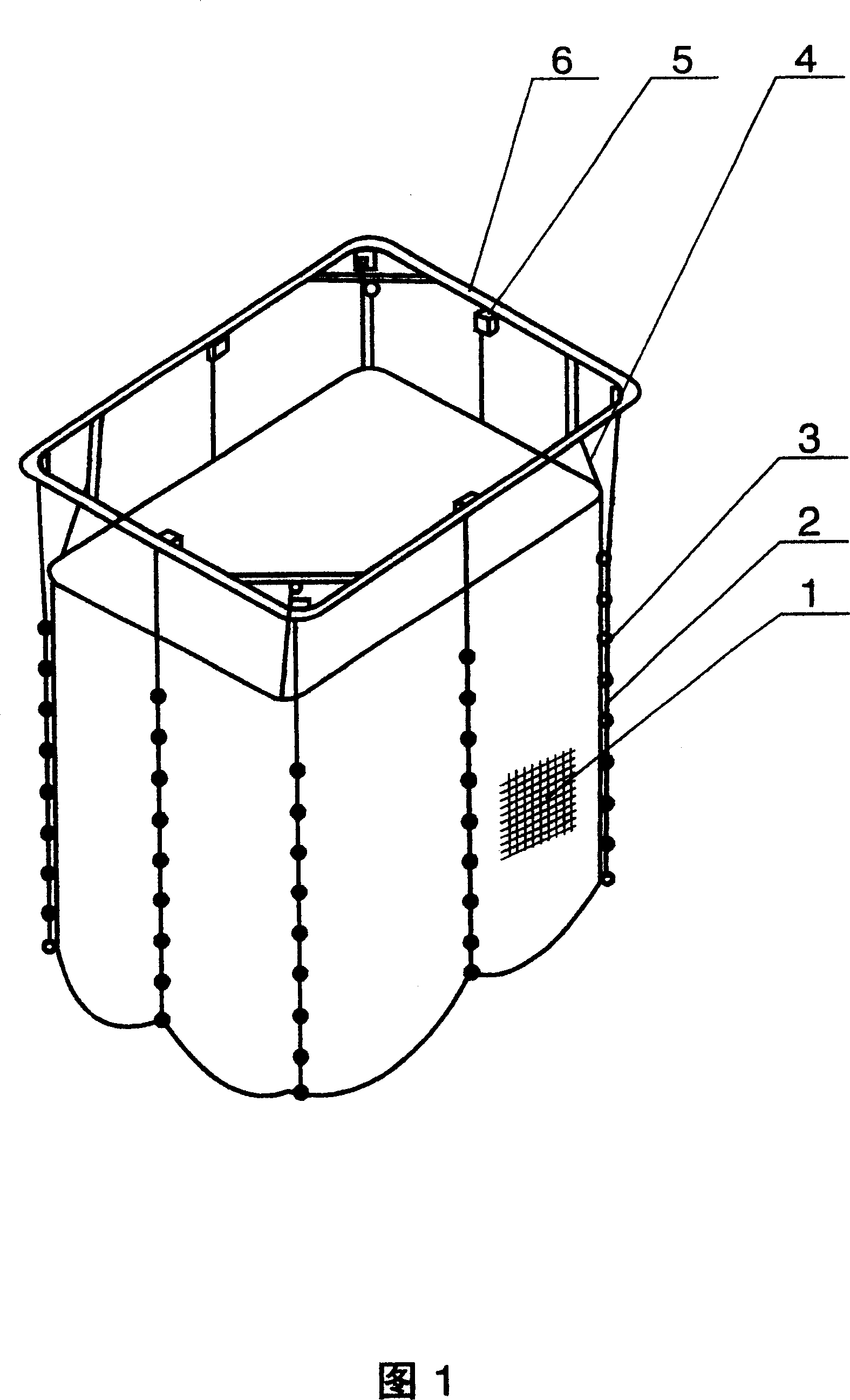
Electric mosquito net elevating mechanism
A technology of electric lifting mechanism and elevator, which is applied in the direction of clockwork mechanism, application, household appliances, etc., and can solve problems such as failure, inability to land, and difficulty in unraveling
- Summary
- Abstract
- Description
- Claims
- Application Information
AI Technical Summary
Problems solved by technology
Method used
Image

Examples
Embodiment 1
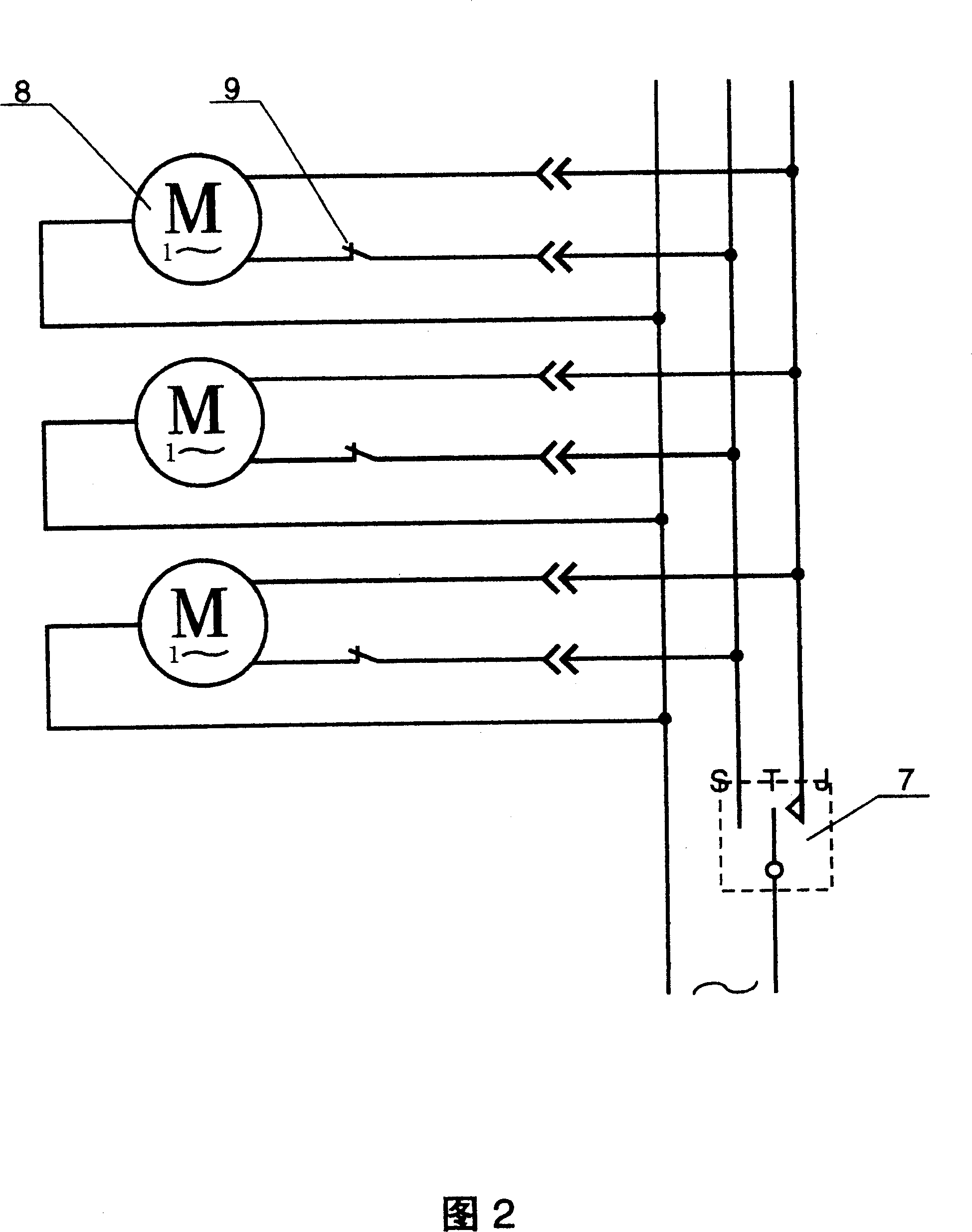
[0053] Fig. 2 is the circuit diagram that embodiment one adopts single-phase reversible AC motor, and the electric element of each elevator comprises, a motor 8, a travel switch 9, and the single-phase reversible permanent-magnet synchronous motor of electric capacity phase-shifting is suitable for AC motor, power Preferably 3 to 10 watts, the travel switch 9 is connected in series with the forward rotation circuit of the motor 8 as the power input end for the elevator 5 to rise, and the reverse circuit of the motor 8 is used as the power input end for the elevator 5 to descend;
[0054] The reversing switch 7 is a unipolar changeover switch with a moving contact S and an elastically returning moving contact J. For the convenience of the following description, the contact S connected to the forward rotation circuit of the motor is called the lifting gear, and the contact J is called the landing gear;
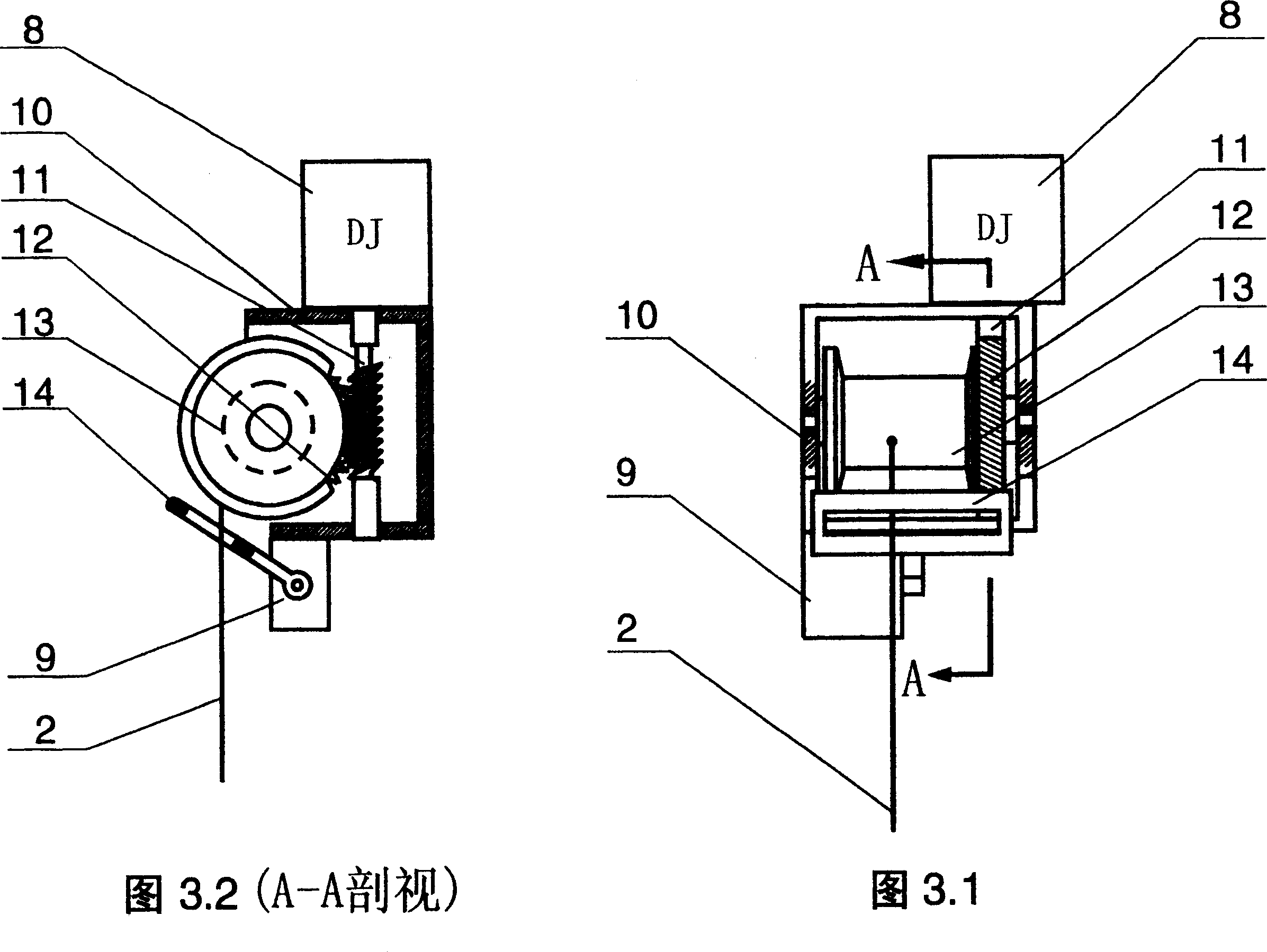
[0055] In Figure 3.1 and Figure 3.2, the components that make up the lift i...
Embodiment 2
[0059] Fig. 4 is the scheme of embodiment two, and this is the scheme that adopts gear transmission and electric control braking device as above-mentioned transmission device and braking device, and Fig. 4 has only drawn the parts of gear 15 and electric control braking device, The gear 15 can be any gear of the gear transmission between the motor 8 and the reel 13, and other parts are omitted, and the main parts of the braking device include a gear 15, a braking tooth 16, a limit pin 17, Hinge pin 18, electromagnet 19, electromagnetic coil 20, spring 21, reel 13 is connected with gear 16; The swing of braking tooth 16 around its hinge pin 18 is limited by limit pin 17, and spring 21 pulls braking tooth 16 Keep it close to the position of the limit pin 17, where the brake teeth 16 protrude between the teeth of the gear 15 so that it cannot be reversed. 16 is sucked away from gear 15; The difference between the internal circuit of the elevator 5 of the present embodiment and Fi...
Embodiment 3
[0062] In Figure 5.1 and Figure 5.2, the elevator 5 is composed of a housing 10, a motor 8, a reel 13, a travel switch 9, a contact 14 of the travel switch 9, and an electronically controlled clutch as the above-mentioned transmission device and braking device. By driven chainring 28, driving chainring 26, braking tooth 16a, back-moving spring 21a, hinge pin 18a, limit pin 17a, axis 27, push spring 24, motor output gear 22, electromagnet 23, electromagnetic coil 25 Composition; the clutch in Fig. 5 is in disengagement state, and reel 13 is coaxially fixedly connected with driven toothed disc 28 and can rotate on central shaft 27, and two surfaces between driven toothed disc 28 and driving toothed disc 26 have Ring-shaped tooth surfaces that can mesh with each other. The active toothed disc 26 can rotate on the central axis 27 and move forward and backward along the central axis 27. The periphery of the active toothed disc 26 has teeth that mesh with the gear 22. The braking tee...
PUM
 Abstract
Description
Claims
Application Information