Bar collecting device

A collection device and bar technology, which is applied in the field of steel rolling equipment, can solve the problems of bar winding cross, production cost and power consumption, and affect production efficiency

Inactive Publication Date: 2018-09-07
盐城市联鑫钢铁有限公司
View PDF4 Cites 0 Cited by
  • Summary
  • Abstract
  • Description
  • Claims
  • Application Information

AI Technical Summary

Problems solved by technology

[0002] After the bar rolling is completed, the product needs to be collected and packaged. During the collection process, due to the height difference between the transfer chain and the steel collecting trough, when the bar falls from the transfer chain to the steel collecting trough, due to the relatively long length, the maximum generally reaches 12 meters, if the two ends are not dropped at the same time, one end will swing, causing the bars to intertwine and cross in the steel collecting channel, th

Method used


Image

  • Bar collecting device
  • Bar collecting device

Examples


Embodiment Construction

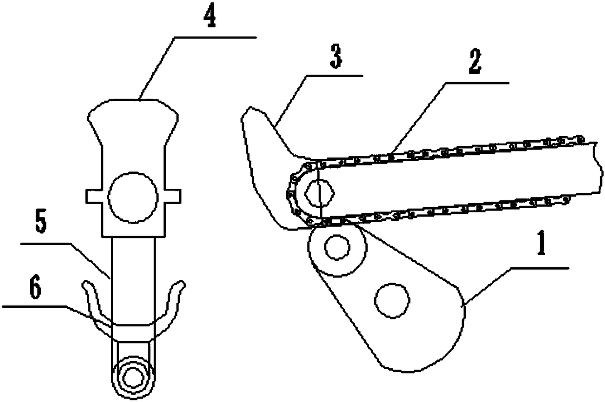
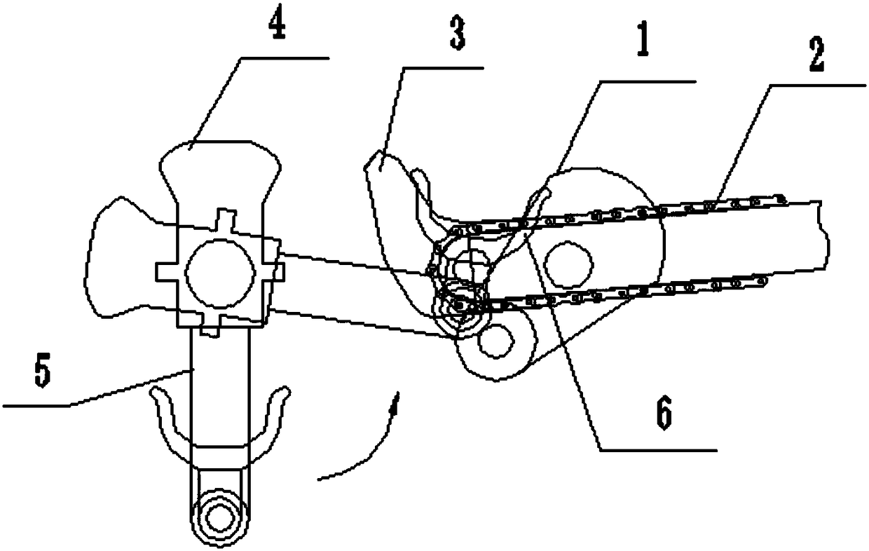
[0018] A bar collection device, which includes a chain conveying mechanism 2, a push plate 1 and a collecting mechanism, two baffles 3 are fixedly installed at the end of the chain conveying mechanism, the push plate is hinged below the chain conveying mechanism, The collection mechanism is located in front of the chain conveying mechanism, and includes a swing rod 5, a counterweight 4 fixedly mounted on the top of the swing rod and a supporting plate 6 fixedly mounted on the bottom of the swing rod.

[0019] Further, the push plate is fan-shaped.

[0020] Further, the push plate is driven to rotate by an air cylinder (not shown).

[0021] Further, the supporting plate is U-shaped.

[0022] Further, the swing rod is driven to rotate by a motor (not shown).

[0023] As a kind of rod collecting device protected by the present invention includes a chain conveying mechanism, a push plate and a collecting mechanism, two baffles are fixedly installed at the end of the chain convey...


PUM


Abstract

The invention relates to the field of rolling equipment, in particular to a bar collecting device which comprises a chain conveying mechanism, a push plate and a collecting mechanism. Two baffle plates are fixedly arranged at the tail end of the chain conveying mechanism; the push plate is hinged under the chain conveying mechanism; and the collecting mechanism is arranged in front of the chain conveying mechanism, and comprises an oscillating bar, a counter weight fixedly arranged on the upper part of the oscillating bar, and a support plate fixedly arranged on the lower part of the oscillating bar. The device provided by the invention is simple in structure and convenient to operate, prevents products from intercross enwinding and prevents a surface oxide layer protection peel from falling off.

Description

technical field [0001] The invention relates to the field of steel rolling equipment, in particular to a rod collecting device. Background technique [0002] After the bar rolling is completed, the product needs to be collected and packaged. During the collection process, due to the height difference between the transfer chain and the steel collecting trough, when the bar falls from the transfer chain to the steel collecting trough, due to the relatively long length, the maximum generally reaches 12 meters, if the two ends are not dropped at the same time, one end will swing, causing the bars to intertwine and cross in the steel collecting channel, thus affecting the packaging quality. At the same time, using a vibrating machine to shake and vibrate back and forth to prevent the rods from being entangled will cause the oxide skin protective layer on the surface of the finished product to fall off, reduce the appearance quality and anti-corrosion performance of the product, a...

Claims


Application Information

Patent Timeline
IPC IPC(8): B65G47/88B65G47/52
CPCB65G47/8838B65G47/52
Inventor 沈云亭谢碧松陈勋姚建赵根社韩凯祖吴则国麻成成王康
Owner 盐城市联鑫钢铁有限公司
Why Eureka
Try Eureka