[0002] With the improvement of bicycle
manufacturing technology, the number of users of multi-stage or continuously variable speed bicycles is also increasing. Generally, a variable speed bicycle is equipped with a variable speed
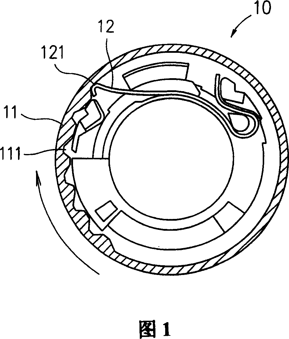
handle on the handlebar of the bicycle. By adjusting the variable speed handle, a wire can be pulled to control the engagement of the chain guide wheel. The corresponding toothed discs of the chainring group are used to achieve the purpose of shifting. There are many known structures of the shifting grip, such as "speed shifting operating device for bicycles" (Taiwan Invention Patent Publication No. 522969), the shifting operating device 10 mainly has a main body 11 and an elastic piece 12. The main body 11 has a positioning section 111 in a continuous concave-convex shape. When the main body 11 is rotated, the end 121 of the elastic piece 12 can be changed to fit in different positioning sections 111. To achieve the purpose of speed change, however, since the state of the shrapnel 12 towards the positioning section 111 has a skewed directionality, when the main body 11 rotates
clockwise, the positioning section 111 and the end 121 form a resistance state, resulting in a large The resistance of the main body 11 makes the rotation of the main body 11 extremely unsmooth. Not only does it feel stiff and uncomfortable, but also the parts wear a lot. Usually, when the main body 11 rotates
clockwise, it is in the downshift direction. Easier in downshifts and harder in downshifts
[0003] Other variable speed operating devices disclosed in US Patent US5524501 "
DETENT SPRING FOR ROTATABLE GRIPACTUATING
SYSTEM" and US Patent US5662000 "
DETENT SPRING FOR ROTATABLE GRIPACTUATING
SYSTEM", when the body rotates in one direction, all will produce the aforementioned impedance phenomenon with the shrapnel, not only It feels stiff and uncomfortable, and the parts wear a lot. Since its structure is similar to the aforementioned conventional structure, it will not be described here.
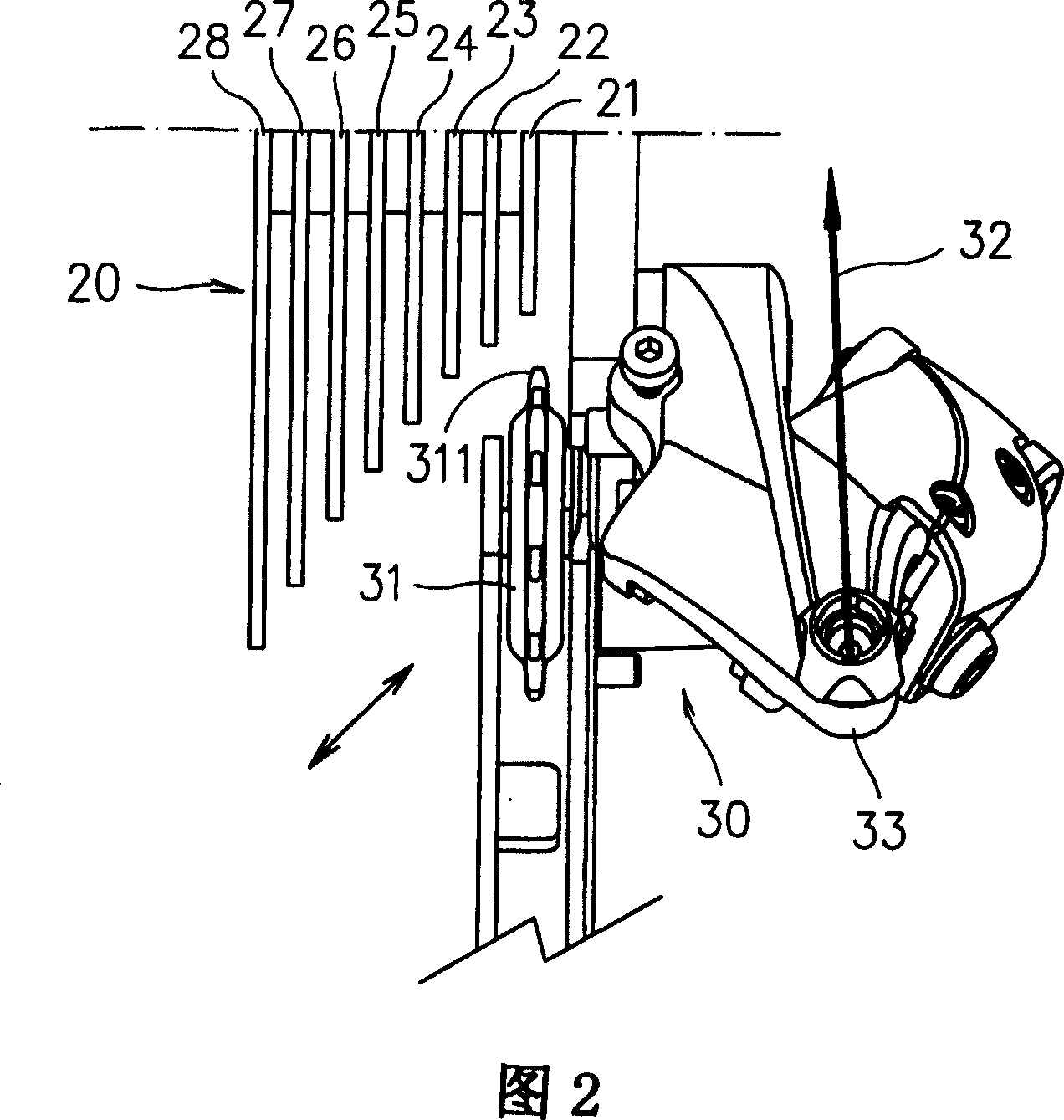
[0004] Please refer to Fig. 2 again at the same time, the traditional transmission mechanism cooperates the chainring set 20 by the chain guide wheel 31 of the rear derailleur 30, the circumference of the chain guide wheel 31 has teeth 311, the rear derailleur 30 is connected to a wire 32, and the wire 32 It is pierced by a shell 33 and then connected to the body 11 of the above-mentioned speed change operation device 10. The chainring set 20 has chainrings 21~28 with different diameters. The diameters of the chainrings 21~28 are from the outside of the bicycle to the inside. Gradually expand, when the control body 11 pulls the wire 32 to drive the chain guide wheel 31 to move, the chain guide wheel 31 can be adjusted to move to the appropriate chainring 21~28, and at the same time shift the chain to the appropriate corresponding tooth plate to achieve speed change For the purpose, please refer to Fig. 2A at the same time, taking the three toothed discs 21, 22, 23 as an example, when the chain guide wheel 31 moves from the small
diameter toothed disc 21 to the large
diameter toothed disc 23, it is an upshift (i.e. deceleration) state, on the contrary, when the chain guide wheel 31 moves towards the tooth disc 21 of the small disk
diameter from the chainring 23 of the large
disc diameter, it is the downshift (i.e. acceleration) state. The most ideal situation is that the chain guide wheel 31 can be accurately moved to the bottom of the corresponding chainring, so that the chain can be quickly wound up or down. However, the actual situation is that due to the friction in the transmission, the shifting handle, and the friction between the wire 32 and the housing 33, it often leads to the chain guide. The wheel 31 cannot be positioned accurately. As shown in FIG. 2, if the chain guide wheel 31a is originally located under the chainring 21, when the chain guide wheel 31a is adjusted to move toward the chainring 22 (i.e. shift up), the position of the chain guide wheel 31a will The position will be slightly to the right (31a'). If the chain guide wheel 31b is originally located under the toothed plate 23, when the chain guide wheel 31b is adjusted to move toward the toothed plate 22 (i.e. down gear), the position of the chain guide wheel 31b will change. Slightly to the left (31b'), in order to improve this deviation phenomenon, the general shifting handle or transmission is equipped with a wire tightness adjustment device to adjust the tightness of the wire 32, however, if the position of the upper gear is adjusted accurately, it will affect the lower gear. The gear position 31b' is more to the left. Similarly, if the lower gear position is adjusted accurately, it will affect the upper gear position 31a' to be more to the right, making it more difficult to wind up and down the chain, which causes the reason that it cannot be adjusted at the same time. The reason is that the traditional shifting operating device only has a shrapnel for positioning, and its positioning distance is fixed, so the upper gear and the lower gear interfere with each other and cannot be adjusted independently. As far as the above-mentioned conventional structures are concerned, there are such disadvantages
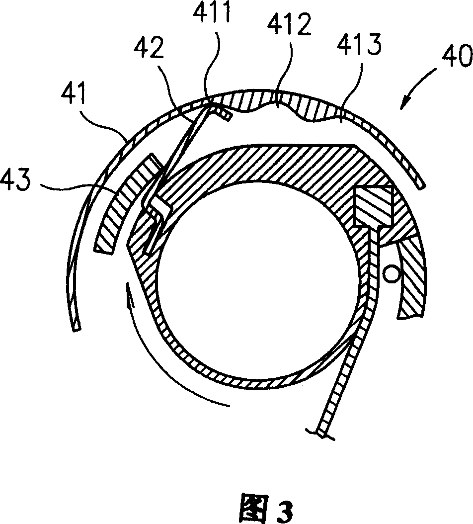
[0005] Please refer to Fig. 3 again, it is U.S. Patent US6021688 " TWIST HANDLEBAR FOR CONTROLLINGTHE DERAILLEUR OF A BICYLE ", this variable speed operating device 40 is provided with a protrusion 43, when the main body 41 rotates
clockwise (when retreating), the protrusion 43 can be slightly lowered Press the elastic piece 42 to separate the elastic piece 42 from the positioning
ratchet 411 moderately, thereby improving the problem of unsmooth rotation of the reverse gear. When the
ratchet 412 is used, it is necessary to precisely control the palm to feel whether the shrapnel 42 rebounds in the positioning ratchet 412. In other words, once the speed of the palm rotation back gear is faster than the rebound speed of the shrapnel 42, the shrapnel 42 may miss the correct gear position. And until the next positioning ratchet 413 is rebounded and positioned, it will not be the desired result of the rider. This is the hidden deficiency of this known structure. In addition, because this known structure is only provided with a shrapnel 42, it is still Unable to solve the above-mentioned problem that the adjustment of the upper and lower gear positions cannot be accurately aligned


