Elevator and traction sheave of elevator
A cladding and rope groove technology, applied in the field of elevator traction sheave, can solve the problem that the embedded parts must be replaced regularly.
- Summary
- Abstract
- Description
- Claims
- Application Information
AI Technical Summary
Problems solved by technology
Method used
Image

Examples
Embodiment Construction
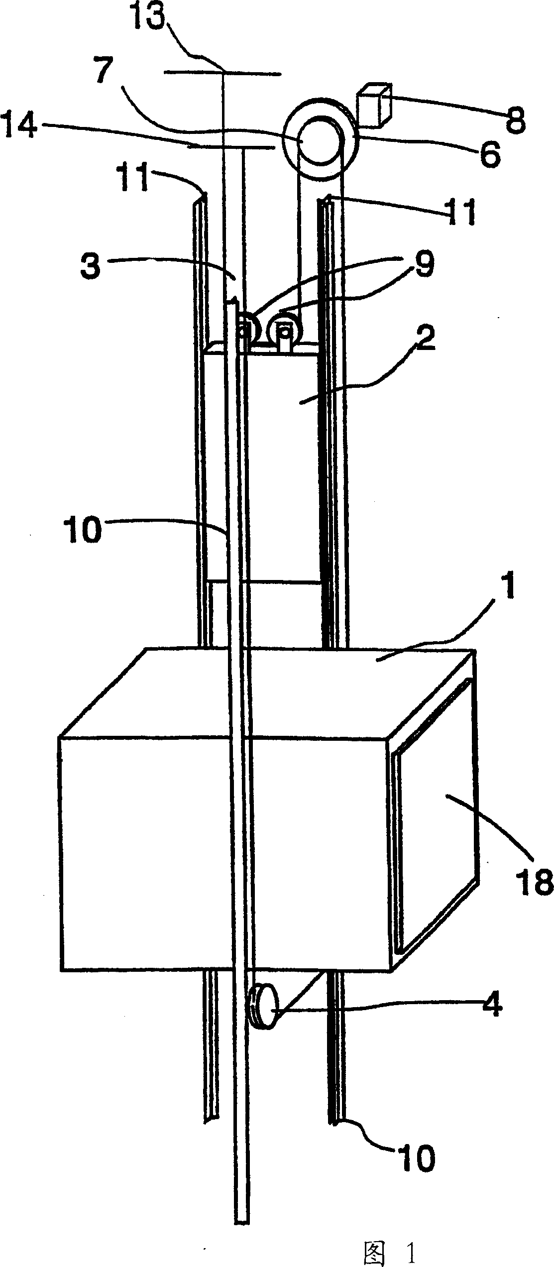
[0041] Figure 1 is a schematic diagram of the structure of an elevator. The elevator is preferably an elevator without a machine room, in which the drive machine 6 is placed in the elevator shaft, although the invention is also suitable for elevators with a machine room. The walking situation of elevator hoisting rope 3 is as follows: one end of each rope is fixed on the anchor seat 13 in the upper shaft shaft top that is positioned at the top of counterweight 2 paths, and counterweight then moves along counterweight guide rail 11. From the anchorage the ropes run downwards and around diverting pulleys 9 which hang the counterweight, which are rotatably mounted on the counterweight 2 and from there the ropes 3 run upwards to the traction ropes of the driving machine 6 Wheel 7 walks around the traction sheave along each rope groove on the sheave. From the traction sheave 7, the ropes 3 then run downwards to the elevator car 1 moving along the car guide rail 10, where the eleva...
PUM
 Abstract
Description
Claims
Application Information
 - R&D
- Intellectual Property
- Life Sciences
- Materials
- Tech Scout
- Unparalleled Data Quality
- Higher Quality Content
- 60% Fewer Hallucinations
Browse by: Latest US Patents, China's latest patents, Technical Efficacy Thesaurus, Application Domain, Technology Topic, Popular Technical Reports.
© 2025 PatSnap. All rights reserved.Legal|Privacy policy|Modern Slavery Act Transparency Statement|Sitemap|About US| Contact US: help@patsnap.com