Memory system control method
A control method and storage system technology, applied in the field of memory address control, can solve the problems of DMA controller process efficiency reduction, processing man-hours or processing time increase, etc.
- Summary
- Abstract
- Description
- Claims
- Application Information
AI Technical Summary
Problems solved by technology
Method used
Image

Examples
no. 1 example
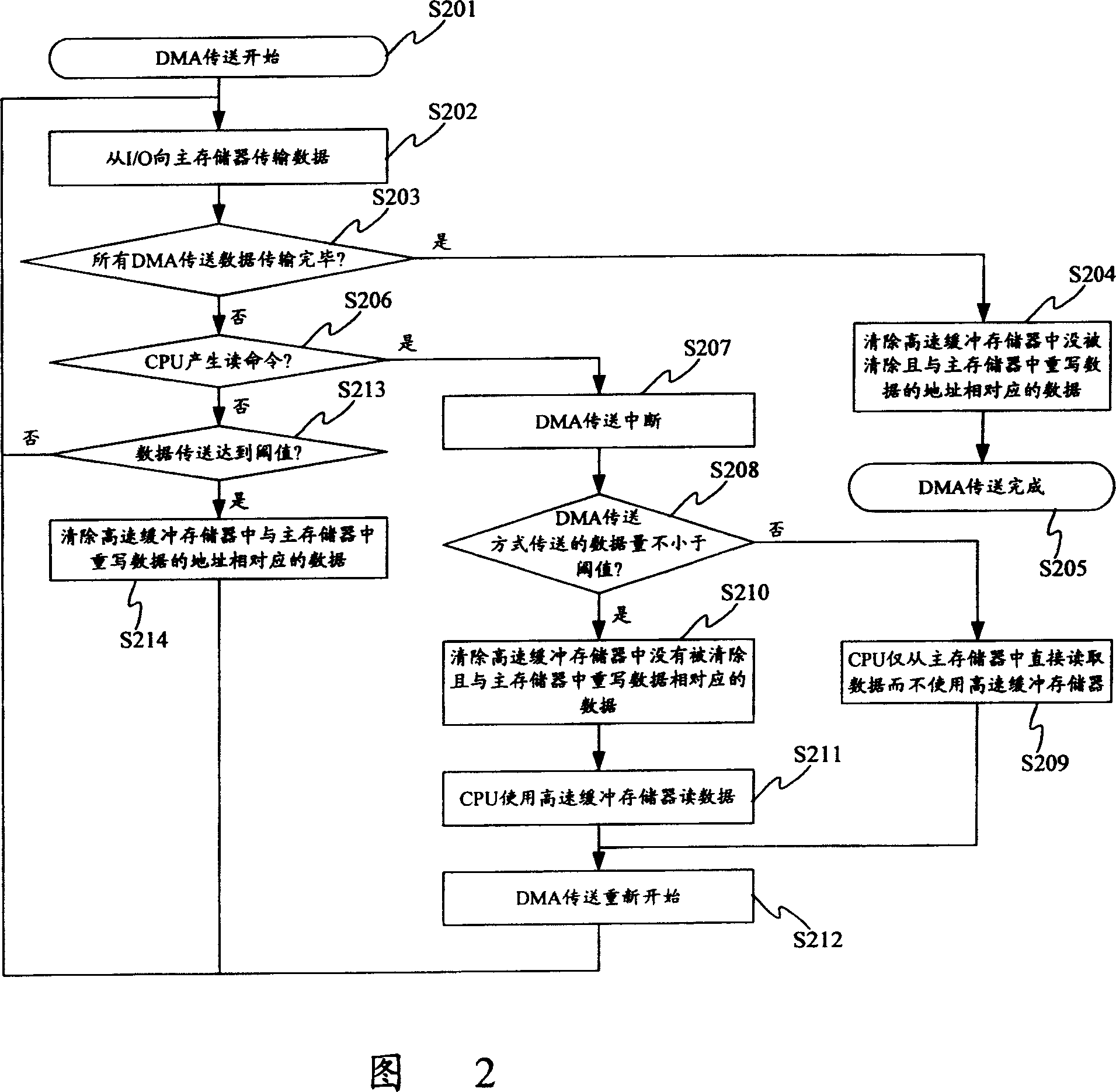
[0030] FIG. 2 shows the general outline of the control method of the first embodiment of the present invention, and is also a flow chart of the process from the start of DMA transfer to the completion of DMA transfer. Next, its operation will be described.
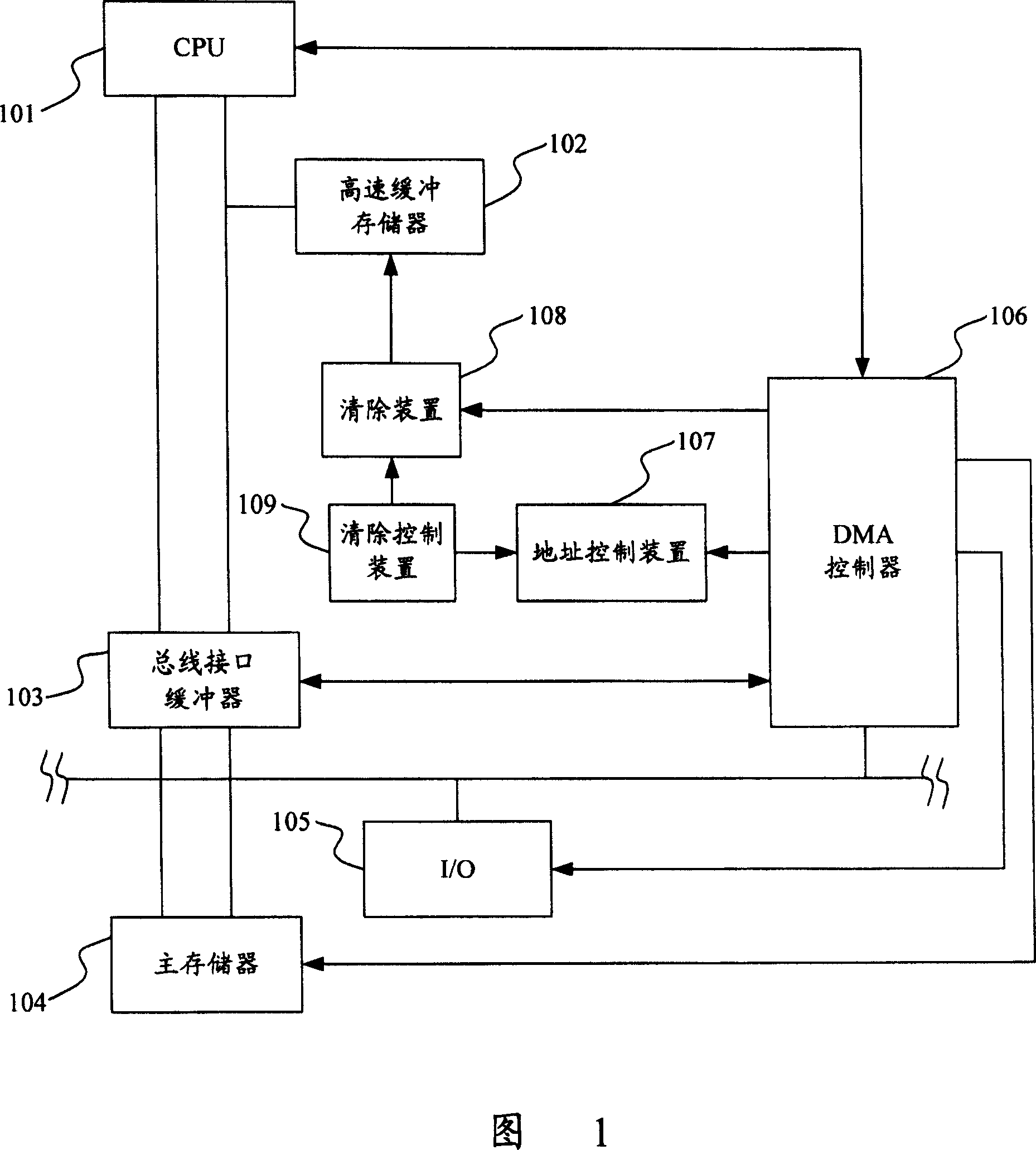
[0031] First, when a DMA transfer request starts, the DMA controller 106 sends a hold signal for a hold operation to bus masters such as the CPU 101 and the bus interface buffer 103 . In response to the hold signal, the CPU 101 and the bus interface buffer 103 return a hold confirmation signal to the DMA controller 106, so that the DMA controller 106 starts DMA transfer (S201). The DMA controller 106 transfers the data to be transferred to the main memory through the I / O 105 to write the data in the main memory (S202). During this period, when all the data transmitted by DMA has been completely transmitted (S203), the DMA controller controls the clearing means so that the clearing is performed on the data that has not bee...
no. 2 example
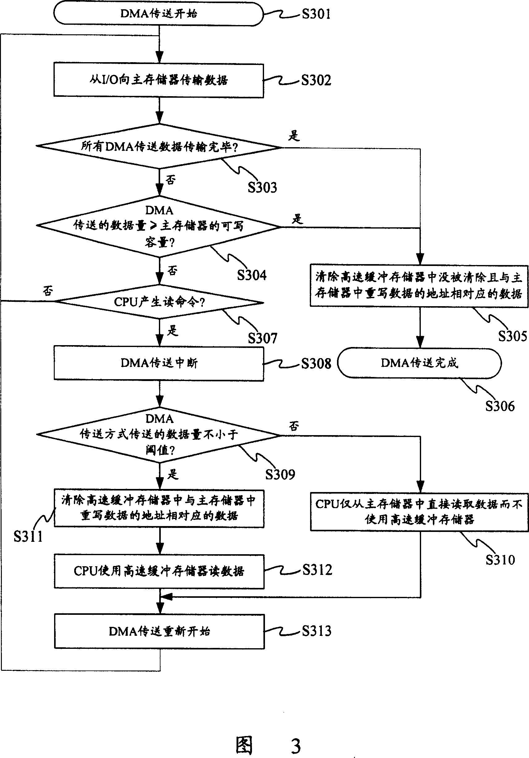
[0040] Next, a second embodiment of the present invention will be described. FIG. 3 is a flow chart showing the general outline from the start of the DMA transfer to the completion of the DMA transfer according to the present embodiment. Next, its operation will be described.
[0041] First, when DMA transfer starts, the DMA controller 106 sends a hold signal for a hold operation to bus masters such as the CPU 101 and the bus interface buffer 103 . In response to this signal, the CPU 101 and the bus interface buffer 103 return a hold confirmation signal to the DMA controller 106, so that the DMA controller 106 starts DMA transfer (S301). The DMA controller 106 transfers the data to be transferred to the main memory 104 through the I / O 105 to write the data in the main memory 104 (S302). During this period, when all the data transferred by DMA have been completely transferred (S303), or when the amount of data transferred to the main memory 104 by the DMA transfer method reac...
no. 3 example
[0048] Next, a third embodiment of the present invention will be described. In this embodiment, a first-in-first-out (FIFO) memory of a ring buffer is used as the main memory of the cache memory system in the first embodiment. Hereinafter, the main memory 101 in FIG. 1 is regarded as the FIFO memory of the ring buffer. FIG. 5 is a diagram showing the status of addresses in the main memory 104. As shown in FIG. In addition, the control method of this embodiment is similar to that of the first embodiment, and this embodiment is described using the flow charts shown in FIG. 2 , FIG. 1 and FIG. 5 .
[0049] First, DMA transfer starts, and the DMA controller 106 sends a hold signal for a hold operation to bus masters such as the CPU 101 and the bus interface buffer 103 . In response to the hold signal, the CPU 101 and the bus interface buffer 103 return a hold confirmation signal to the DMA controller 106, so that the DMA controller 106 starts DMA transfer (S201). Also, the DMA ...
PUM
 Abstract
Description
Claims
Application Information
 - R&D
- Intellectual Property
- Life Sciences
- Materials
- Tech Scout
- Unparalleled Data Quality
- Higher Quality Content
- 60% Fewer Hallucinations
Browse by: Latest US Patents, China's latest patents, Technical Efficacy Thesaurus, Application Domain, Technology Topic, Popular Technical Reports.
© 2025 PatSnap. All rights reserved.Legal|Privacy policy|Modern Slavery Act Transparency Statement|Sitemap|About US| Contact US: help@patsnap.com