Petroleum hydrocarbon catalytic conversion method
A catalytic conversion method and a technology for petroleum hydrocarbons, which are applied in the field of catalytic transformation of petroleum hydrocarbons, can solve problems such as ineffective contact problems, and achieve the effects of reducing dry gas yield, improving product properties, and enhancing gas-solid contact efficiency.
- Summary
- Abstract
- Description
- Claims
- Application Information
AI Technical Summary
Problems solved by technology
Method used
Image

Examples
Embodiment approach A
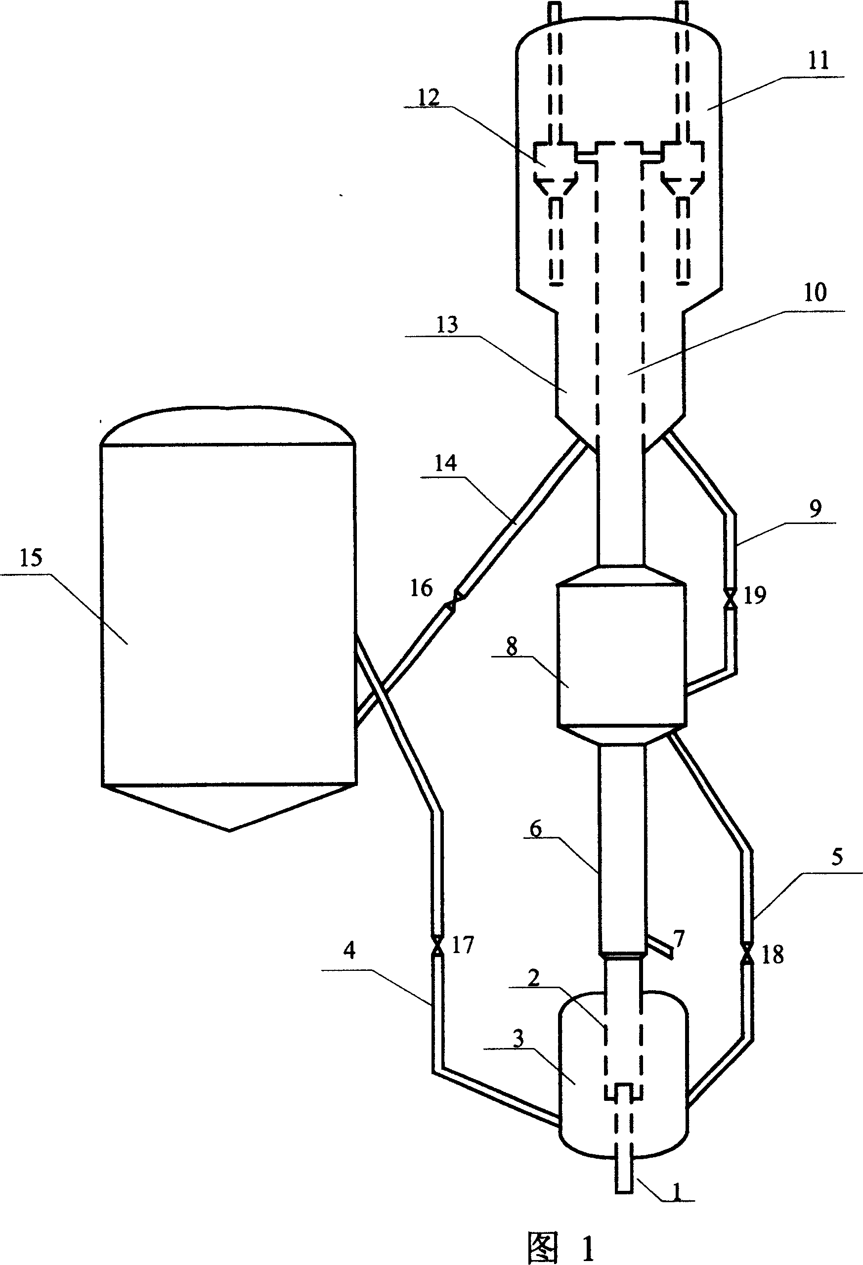
[0020] Embodiment A: As shown in Figure 1, for the variable-diameter riser reactor described in ZL99105903.4, a mixing zone is provided at the bottom of the reactor. Its structural characteristics are: along the vertical direction from bottom to top, there are mutually coaxial mixing zone, pre-lifting section, first reaction zone, second reaction zone with enlarged diameter, and outlet zone with reduced diameter. The size of the mixing zone is equivalent to the stripper in the catalytic cracking unit, coaxial with the riser, and placed at the bottom of the riser. The high-temperature regenerant from the regenerator and the carbon-carrying agent returned from the second reaction zone are mixed in the mixing zone, and the admixture contacts and reacts with the feed oil, which can increase the agent-to-oil ratio and reduce the dry gas yield; Ascends and reacts with oil and gas, and enters the second reaction zone. Part of the second reaction zone with charcoal agent returns to the mi...
Embodiment approach B
[0021]Embodiment B: For a riser + fluidized bed combined reactor (the fluidized bed is located at the top of the riser), a mixing zone is provided at the bottom of the reactor. Its structural characteristics are: along the vertical direction from bottom to top, there are mutually coaxial mixing zone, riser (first reaction zone), and fluidized bed (second reaction zone). The size of the mixing zone is equivalent to the stripper in the catalytic cracking unit, coaxial with the riser, and placed at the bottom of the riser. The high-temperature regenerant from the regenerator and the carbon-carrying agent returned from the second reaction zone are mixed in the mixing zone, and the mixture is contacted and reacted with the feed oil, which can increase the agent-to-oil ratio and reduce the dry gas yield; And the reaction oil and gas move upward, react, and enter the second reaction zone. Part of the second reaction zone with charcoal agent returns to the mixing zone. The remaining catal...
Embodiment
[0027] This example illustrates: the product distribution and product properties obtained by using the method provided by the present invention to carry out the catalytic conversion reaction of hydrocarbon oil.
[0028] The process flow of the medium-sized catalytic cracking unit is shown in Figure 1. The preheated feed oil is injected into the first reaction zone of the reactor through line 7, and contacts and reacts with the mixing agent in the reaction zone. The mixing agent is produced from the second reaction zone. The 495℃ charcoal agent and 700℃ regenerant returned from the zone are mixed in the mixing zone at a ratio of 0.05:1. The bed density in the mixing zone is 300kg / m 3 . The reaction temperature in the first reaction zone is 545°C, the reaction time is 1 second, and the catalyst-oil ratio is 5.5:1. The mixture of oil and gas and catalyst goes upward into the second reaction zone, and returns part of the spent catalyst from the stripping section to the second reaction...
PUM
| Property | Measurement | Unit |
|---|---|---|
| density | aaaaa | aaaaa |
| density | aaaaa | aaaaa |
Abstract
Description
Claims
Application Information
 - R&D
- Intellectual Property
- Life Sciences
- Materials
- Tech Scout
- Unparalleled Data Quality
- Higher Quality Content
- 60% Fewer Hallucinations
Browse by: Latest US Patents, China's latest patents, Technical Efficacy Thesaurus, Application Domain, Technology Topic, Popular Technical Reports.
© 2025 PatSnap. All rights reserved.Legal|Privacy policy|Modern Slavery Act Transparency Statement|Sitemap|About US| Contact US: help@patsnap.com