

Metallic damping pad and its making method
A manufacturing method and technology of vibration damping pads, applied in the direction of shock absorbers, shock absorber-spring combinations, shock absorbers, etc., can solve problems such as high and low temperature failure, failure to meet long-term storage and use, and reduce maintenance costs Effect
- Summary
- Abstract
- Description
- Claims
- Application Information
AI Technical Summary
Problems solved by technology
Method used
Image

Examples
Embodiment 1
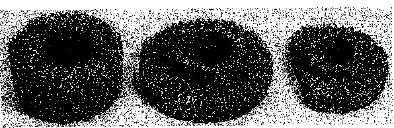
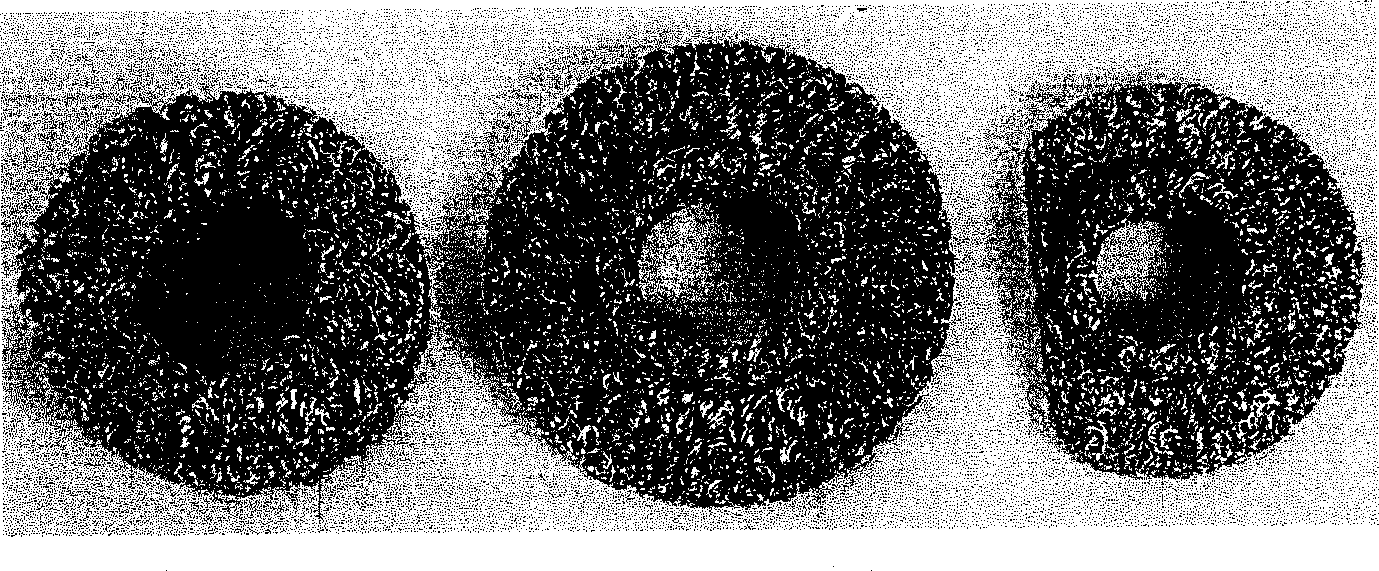
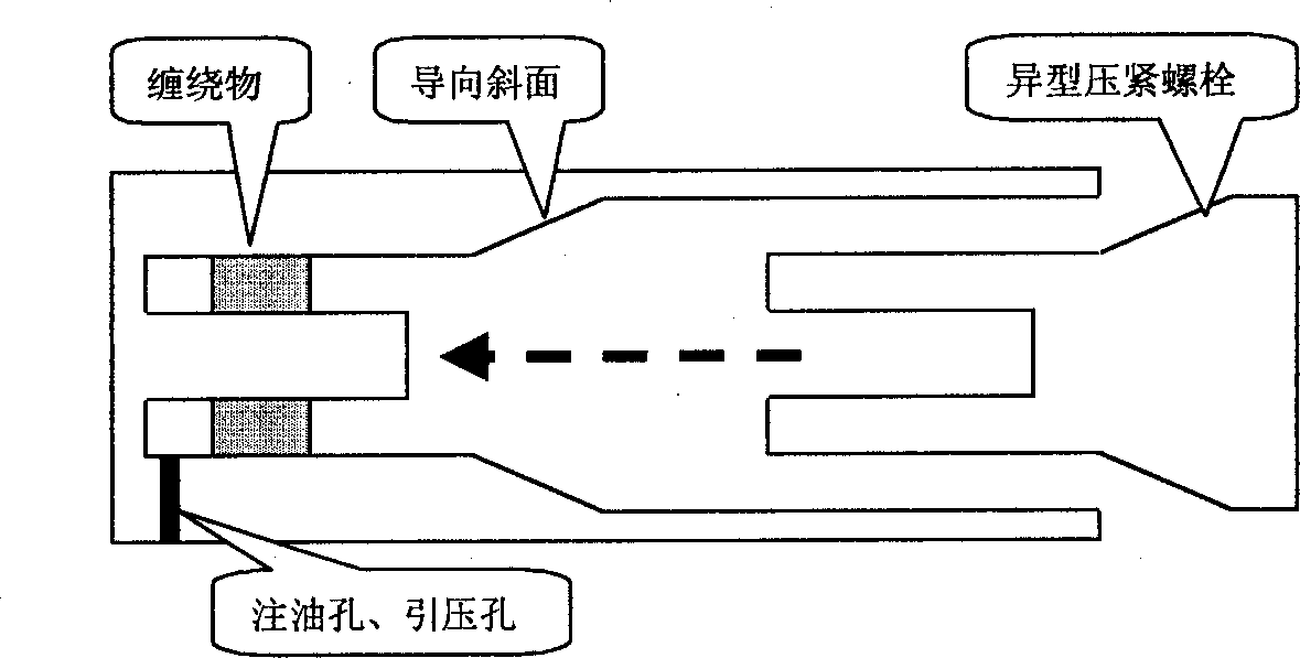
[0013] Circle-shaped shock pads ( figure 1 Left) is to use 0.1mm steel wire to wind a number of 400mm long dense springs on steel wires with a diameter of 1.2mm, and stretch them into slender springs with equal pitch and a pitch of 2mm, which are used as raw materials for vibration damping pads. Subsequently, these springs are wound on the winding tool, the outer diameter of the winding tool is 1.5 times the inner diameter of the metal damping pad, the winding height is 3 times the actual height, and the outer diameter of the winding is 1.5 times the actual outer diameter. Then, the winding (blank) is removed and passed through the forming device ( image 3 ) bell mouth, introduced into the molding device, pressed into a vibration damping pad consistent with the required size, filled with castor oil, placed in a high temperature box, introduced 100MPa pressure, heated to 200°C, and kept at constant temperature and pressure for 3 hours. Finally, release the pressure, cool down...
Embodiment 2
[0015] Conical shock absorber ( figure 1 Middle) is to use 0.1mm steel wire to wind a number of 400mm long dense springs on steel wires with a diameter of 1.5mm, and stretch them into slender springs with equal pitch and a pitch of 2.5mm as the raw material of the vibration damping pad. Subsequently, these springs are wound on the winding tool, the outer diameter of the winding tool is 1.3 times the inner diameter of the metal damping pad, the winding height is 4 times the actual height, and the outer diameter of the winding is 1.4 times the actual outer diameter. Then, remove the winding (blank), pass through the bell mouth of the molding device, introduce it into the molding device, press it into a vibration damping pad consistent with the required size, pour castor oil, put it in a high-temperature box, introduce a pressure of 100MPa, and heat up to 200°C , constant temperature and constant pressure for 3 hours. Finally, release the pressure, cool down, take out the windin...
Embodiment 3
[0017] Shaped shock pad ( figure 1 Right) is to use 0.15mm steel wire to wind a number of 400mm long dense springs on steel wires with a diameter of 3mm, and stretch them into slender springs with equal pitch and a pitch of 3mm, which are used as raw materials for vibration damping pads. Subsequently, these springs were wound on the winding tool, the outer diameter of the winding tool was 1.7 times the inner diameter of the metal damping pad, the height of the winding was 2.5 times the actual height, and the outer diameter of the winding was 1.7 times the actual outer diameter. Then, remove the winding (blank), pass through the bell mouth of the molding device, introduce it into the molding device, press it into a vibration damping pad consistent with the required size, pour castor oil, put it in a high-temperature box, introduce a pressure of 100MPa, and heat up to 200°C , constant temperature and constant pressure for 3 hours. Finally, release the pressure, cool down, take ...
PUM
 Abstract
Description
Claims
Application Information