
Demodulator for processing digital signal

A demodulator and data signal technology, applied in the field of demodulators, can solve problems such as increase in circuit scale, deterioration of carrier regeneration loop characteristics, increase in delay, etc.

Inactive Publication Date: 2002-03-06
NEC CORP
View PDF1 Cites 5 Cited by
  • Summary
  • Abstract
  • Description
  • Claims
  • Application Information

AI Technical Summary

Problems solved by technology

Such an increase in delay will increase the circuit scale, and will lead to deterioration of the feedback control characteristics, especially the characteristics of the carrier regeneration loop.

Method used


Image

  • Demodulator for processing digital signal
  • Demodulator for processing digital signal
  • Demodulator for processing digital signal

Examples


Embodiment Construction

[0106] The best way to practice the invention

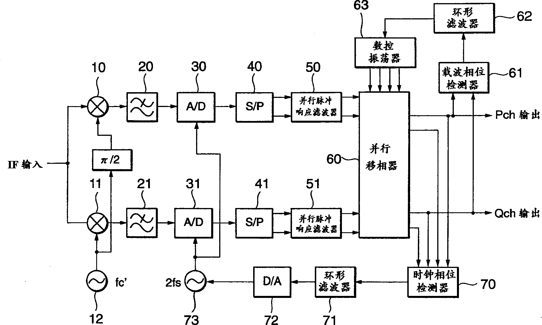
[0107] Such as figure 1 As shown, the demodulator based on the first embodiment of the present invention is a quasi-synchronous detection method.

[0108] The illustrated demodulator receives a quadrature-modulated IF signal, and first performs analog quadrature detection. The IF signal is branched into 2 paths. One of the signals, in the mixer 11, is multiplied by the Lo signal having a frequency fc' output by the local oscillator 12 which is approximately equal to the carrier frequency fc, and then passes through the low-pass filter 21. The other signal, in the mixer 10 , is multiplied by the signal obtained by performing a π / 2 phase shift on the Lo signal output by the local oscillator 12 , and then passes through the low-pass filter 20 . The signals filtered in the low-pass filters 20 and 21 become mutually orthogonal baseband (BB) signals. The channels of these signals are called Pch and Qch, respectively. These signals...


PUM


Abstract

The serial data signal obtained by carrying out an A / D conversion at two times the modulation speed is S / P-converted, at a data ratio of 1:2, into a pair of parallel data signals of the modulation speed. The demodulation process is carried out by parallelly processing the pair of parallel data signals, resulting in that the demodulation speed is equal to the modulation speed. The serial data obtained by carrying out the A / D conversion at four times the modulation speed is S / P-converted at a data ratio of 1:4, and is then similarly subjected to demodulation at the demodulation speed equal to the modulation speed. With this arrangement, the demodulator carrying out the digital signal processing can be applied to communication systems having a high modulation speed.

Description

technical field [0001] The present invention relates to demodulators for demodulating quadrature modulated input signals, in particular to demodulators using digital signal processing techniques. Background technique [0002] With the rapid progress of LSI (Large Scale Integration), attempts to apply digital signal processing techniques to demodulators are underway in the field of high-speed communication systems with modulation speeds such as 10 MHz. A demodulator using digital signal processing technology (hereinafter referred to as a digital demodulator) has many advantages compared with a demodulator composed of an analog circuit. For example, the digital demodulator is not affected by temperature, humidity, or time, and can realize stable quality. In addition, the digital demodulator can be LSI. Furthermore, the digital demodulator not only does not need to be adjusted, but it is also very easy to change the specification. [0003] In order to realize the main functi...

Claims


Application Information

Patent Timeline
IPC IPC(8): H03H17/06H04L27/00H04L27/22H04L27/227
CPCH04L2027/0057H04L27/2273H04L2027/0067H04L27/22H04L2027/0069
Inventor 佐佐木英作
Owner NEC CORP
Learn More