Optical fiber and its mfg. method

An optical fiber and area technology, which is applied in the direction of glass fiber products, clad optical fibers, manufacturing tools, etc., can solve the problems that the transmission loss of optical fiber cannot be reduced, the effect of reducing transmission loss is not obtained, the transmission loss is not reduced or increased on the contrary, etc.

Inactive Publication Date: 2002-04-10
SUMITOMO ELECTRIC IND LTD
View PDF0 Cites 12 Cited by
  • Summary
  • Abstract
  • Description
  • Claims
  • Application Information

AI Technical Summary

Problems solved by technology

[0006] However, it cannot be said that the reduction of optical fiber transmission loss has been sufficiently achieved in the conventionally proposed manufacturing method for obtaining the effect of reducing Rayleigh scattering loss, such as the manufacturing method using the slow cooling process of the above-mentioned heating furnace.
In particular, even with optical fibers produced by the same manufacturing method, when the transmission loss reduction effect is obtained, there are cases where the transmission loss is hardly reduced or increases conversely, and there is a problem that the transmission loss reduction effect is not definitely obtained.

Method used


Image

  • Optical fiber and its mfg. method
  • Optical fiber and its mfg. method
  • Optical fiber and its mfg. method

Examples


Embodiment Construction

[0037] Hereinafter, the best embodiment of the optical fiber of the present invention and its manufacturing method will be described in detail with reference to the drawings. In the description of the drawings, the same elements are given the same symbols, and repeated descriptions are omitted. The dimensional ratios in the drawings do not necessarily correspond to the descriptions.

[0038] First, the first optical fiber and the method for producing the optical fiber of the present invention will be described.

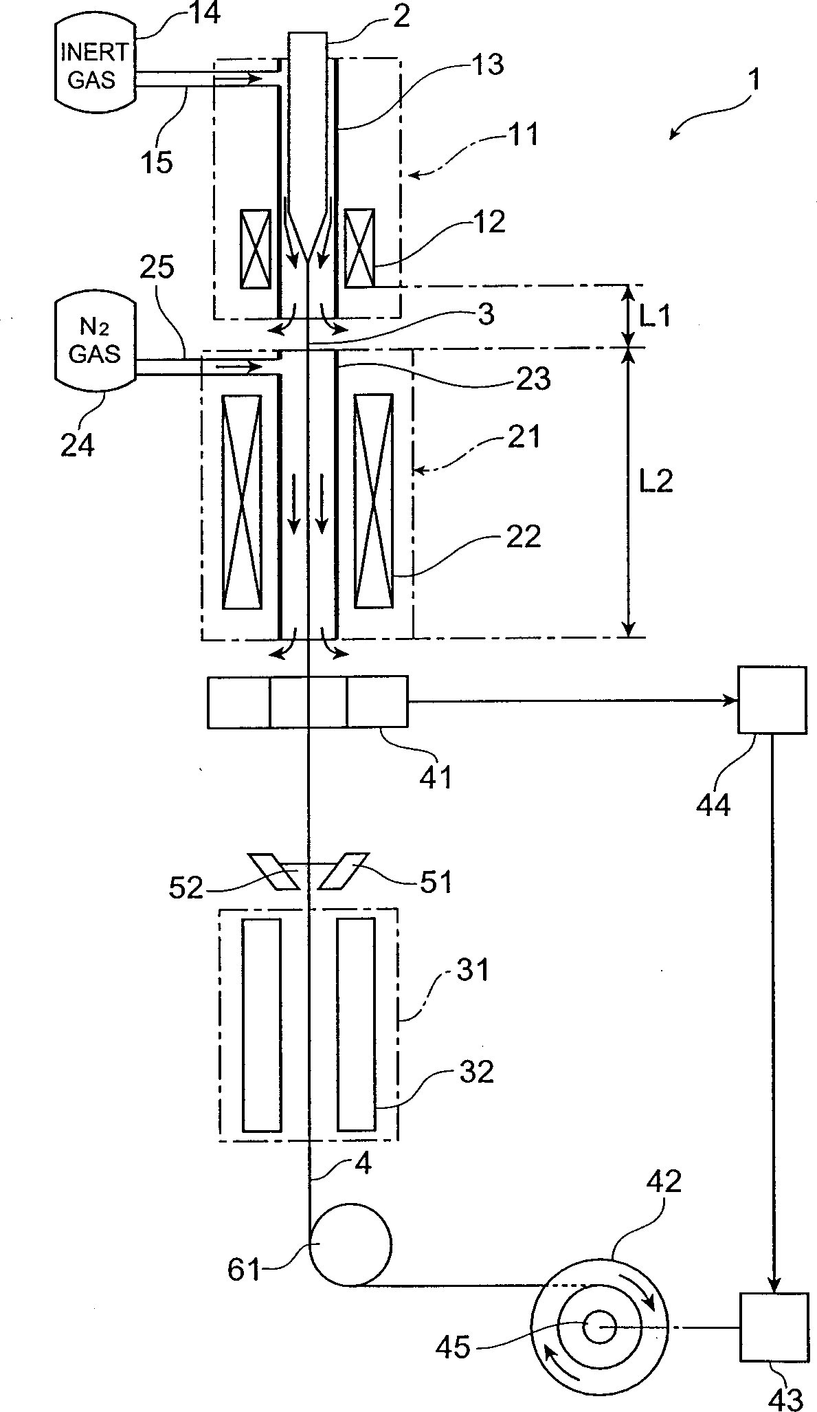
[0039] figure 1 The drawing device 1 shown is a drawing device for drawing quartz glass-based optical fibers, and includes a drawing furnace 11 , a heating furnace 21 for slow cooling, and a resin hardening part 31 . These wire drawing furnace 11, heating furnace 21 and resin hardening part 31 are in the direction of drawing mercerized optical fiber base material 2 ( figure 1 Up and down direction), the wire drawing furnace 11, the heating furnace 21, and the resin...


PUM

PropertyMeasurementUnit
residual stressaaaaaaaaaa
scattering coefficientaaaaaaaaaa

Abstract

An optical fiber preform 2 having a viscosity ratio R eta=eta 0 / eta t of 2.5 or less between the core average viscosity eta 0 and the total average viscosity eta t is prepared, and is drawn by a drawing furnace 11 so as to yield an optical fiber 3, which is then heated to a temperature within a predetermined range so as to be annealed by a heating furnace 21 disposed downstream the drawing furnace 11. Here, upon slow cooling in the heating furnace 21, the fictive temperature Tf within the optical fiber lowers, thereby reducing the Rayleigh scattering loss. At the same time, the viscosity ratio condition of Reta<=2.5 restrains the stress from being concentrated into the core, thereby lowering the occurrence of structural asymmetry loss and the like. Hence, an optical fiber which can reduce the transmission loss caused by the Rayleigh scattering loss and the like as a whole, and a method of making the same can be obtained.

Description

technical field [0001] The present invention relates to optical fibers for transmitting light and methods for their manufacture. technical background [0002] In light transmission using an optical fiber, transmission loss (Rayleigh scattering loss) due to Rayleigh scattering inside the optical fiber becomes a problem. In response to this, an optical fiber capable of reducing Rayleigh emission loss or a method for manufacturing the same has been proposed. [0003] For example, in the document "Sakaguchi, Society of Electronics, Information and Communications Paper 2000 / 1 Vol.J83-CNo.1, pp.30-36", it is described that a Rayleigh Method of scatter reduction. That is, the Rayleigh scattering intensity in the glass is not necessarily determined by the material, but depends on the fictive temperature Tf (FictiveTemperature) representing the fictive temperature of the chaos of the atomic arrangement state in the glass. Specifically, the fictive temperature Tf inside the glass i...

Claims


Application Information

Patent Timeline
Patent Type & Authority Applications(China)
IPC IPC(8): C03B37/027C03B37/029C03B37/15G02B6/02G02B6/036
CPCC03B2201/12G02B6/02G02B6/03627C03B37/029C03B2201/20C03B2201/31C03B37/02718C03B2205/56C03C13/04C03B2203/22C03B37/15C03B37/02727
Inventor 永山胜也大贺裕一齐藤达彦石川真二土屋一郎内山武典
Owner SUMITOMO ELECTRIC IND LTD
Why Eureka
Try Eureka