Single-mode fiber and fabrication method thereof

A single-mode optical fiber, core layer technology, applied in clad optical fibers, glass optical fibers, glass manufacturing equipment, etc., can solve the problems of cumbersome steps, extremely high requirements for fiber drawing, poor uniformity of radial refractive index, etc. Effective area, reduce optical power density, and improve the effect of optical power intensity

Active Publication Date: 2020-02-14
FASTEN HONGSHENG GRP CO LTD +1
View PDF8 Cites 7 Cited by
  • Summary
  • Abstract
  • Description
  • Claims
  • Application Information

AI Technical Summary

Problems solved by technology

[0004] Chinese patent ZL201310409732 discloses a method for preparing a low-loss optical fiber using a pure silicon core scheme. However, due to the pure silicon core design, it is extremely difficult to match the viscosity of the core layer and the cladding layer, and the uniformity of the radial refractive index is poor. Prepared by PCVD in-tube method, the process is complicated and the requirements for fiber drawing are extremely high, which is not conducive to mass production
201510355895.5 discloses a method for preparing a low-loss, large effective area, and high-strength single-mode optical fiber under a germanium-fluorine co-doped core. Although the core rod is prepared by the VAD method, the design of the refractive index profile is very complicated and the steps are cumbersome, which is not conducive to large-scale production. Production

Method used


Image

  • Single-mode fiber and fabrication method thereof
  • Single-mode fiber and fabrication method thereof
  • Single-mode fiber and fabrication method thereof

Examples


Embodiment 1

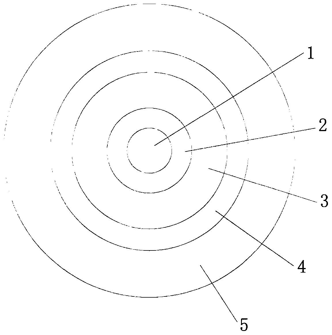
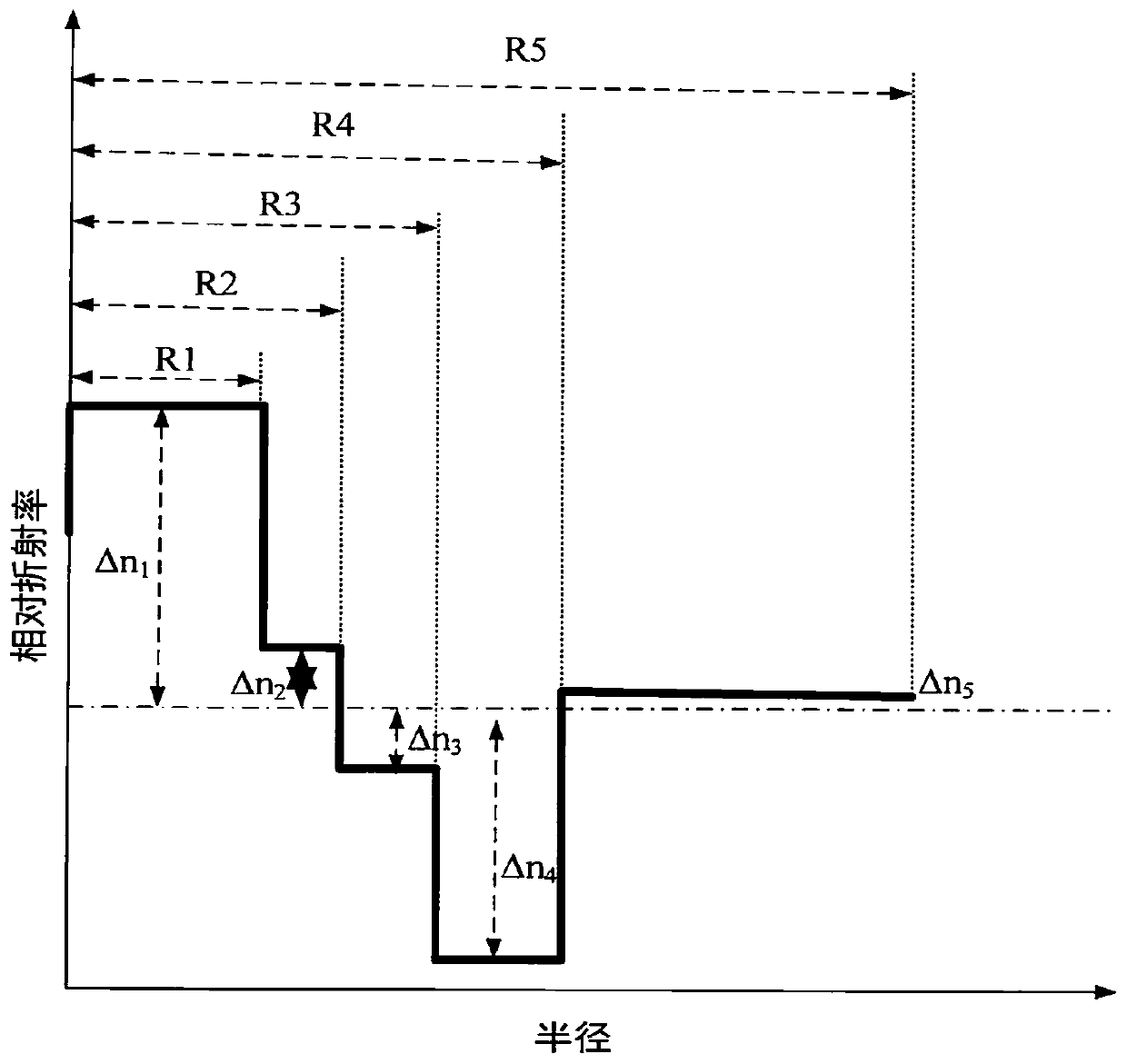
[0059] Such as figure 1 As shown, it is a cross-sectional view of a single-mode optical fiber. The bare optical fiber includes a core layer and an inner cladding layer. The core layer includes a first core layer 1 and a second core layer 2. The radius of the first core layer 1 is R 1 3.5~5.5μm, the relative refractive index difference is 0.2%≤Δ 1 ≤0.35%, second core layer 2 radius R 2 5~7μm, the relative refractive index difference is 0.15%≤Δ 2 ≤0.25%, the refractive index radius of the inner cladding layer 3 is 24 μm to 36 μm, the ratio of the radius of the inner cladding layer 3 to the second core layer 2 is 4.5 to 6, and the relative refractive index difference is -0.12%≤Δ 3 ≤0%. The cladding includes a depressed cladding 4 and an outer cladding 5, the radius of the depressed cladding 4 is 40 μm to 50 μm, and the relative refractive index difference is -0.40%≤Δ 4 ≤-0.28%, the outer cladding 5 is a high-hardness pure quartz sleeve, and the radius of the outer cladding 5 ...

Embodiment 2

[0066] A method for preparing a single-mode optical fiber in which the center of the first core layer in the refractive index profile (RIP) is a flat-top distribution, comprising the steps

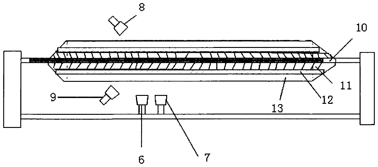
[0067] The core rod is prepared by OVD external vapor deposition. The core rod is divided into the first core layer 1, the second core layer 2 and the inner cladding layer 3. Four torches are set in the deposition lathe, and two vertical torches are set on the pre-installed ceramic target. At 200-300mm directly below the stick (length 2000-2200mm, diameter 6mm-8mm), the vertical blowtorches are arranged in parallel along a straight line, and the spraying direction is perpendicular to the ceramic target rod. They are respectively named the first blowtorch and the second blowtorch; the other two blowtorches are distributed On both sides of the main axis of the pre-installed ceramic target rod, each is pre-fixed at an angle of 45° to the horizontal plane, and they are named the third blowtorch...


PUM

PropertyMeasurementUnit
Radiusaaaaaaaaaa
Modulusaaaaaaaaaa
Diameteraaaaaaaaaa

Abstract

The invention relates to a single-mode fiber and a fabrication method thereof. A bare fiber comprises a core layer and a wrapping layer, wherein the core layer comprises a first core layer, a second core layer and an inner wrapping layer, the relative refractivity difference Delta 1 of the first core layer is more than 0.2% but less than 0.35%, the relative refractivity difference Delta 2 of the second core layer is more than or equal to 0.15% but less than or equal to 0.25%, the refractivity radius of the inner wrapping layer is 24-36 micrometers, the relative refractivity difference Delta 3of the inner wrapping layer is more than or equal to -0.12% but less than or equal to 0%, the wrapping layer comprises a sunken wrapping layer and an external wrapping layer, the relative refractivitydifference Delta 4 of the sunken wrapping layer is more than or equal to -0.40% but less than or equal to -0.28%, and the external wrapping layer is a high-hardness pure quartz sleeve. With the adoption of a method for on-line assembly and drawbenching by two sleeves and a core rod, fiber annealing for many times is performed during the drawbenching process, a coating layer with low modulus is coated in a surface of the fiber, a coating layer with high modulus is coated outside the surface of the fiber, and the fiber with low loss, large effective area and high strength is fabricated. The method is simple, the viscosity of the cord rod can be adjusted according to a demand, the fiber attenuation is reduced without employing a pure silicon core scheme, and production on a large scale is facilitated.

Description

technical field [0001] The invention relates to a single-mode optical fiber and a preparation method thereof. Background technique [0002] As we all know, with the rapid development of optical fiber communication technology, the existing conventional G.652 optical fiber can no longer meet the requirements of high-speed optical communication backbone transmission such as 400G or even 1T. . As the main indicators and symptoms of optical fiber signal transmission, reducing fiber loss and increasing the effective area are generally considered by the industry to be the key factors to improve optical fiber transmission capacity and increase transmission distance. [0003] At present, when the industry is used to prepare low-loss, large-effective-area optical fibers, most of them use VAD and PCVD methods to make core rods, but the refractive index of optical fibers made by VAD is difficult to control, and PCVD cannot improve the single fiber due to the influence of the size of th...

Claims


Application Information

Patent Timeline
IPC IPC(8): G02B6/02G02B6/036C03B37/014C03B37/012C03B37/027
CPCC03B37/014C03B37/027G02B6/02395
Inventor 宋海瑞冯术娟孙周徐亮侯树虎缪振华卞新海韩婷婷
Owner FASTEN HONGSHENG GRP CO LTD
Why Eureka
Try Eureka