Mobile communication base station equipment

A technology of mobile communication base stations and equipment, which is applied in wireless communication, network planning, power management, etc., and can solve problems such as waste of radiation power and interference with base stations

Inactive Publication Date: 2002-04-24
NTT DOCOMO INC
View PDF0 Cites 88 Cited by
  • Summary
  • Abstract
  • Description
  • Claims
  • Application Information

AI Technical Summary

Problems solved by technology

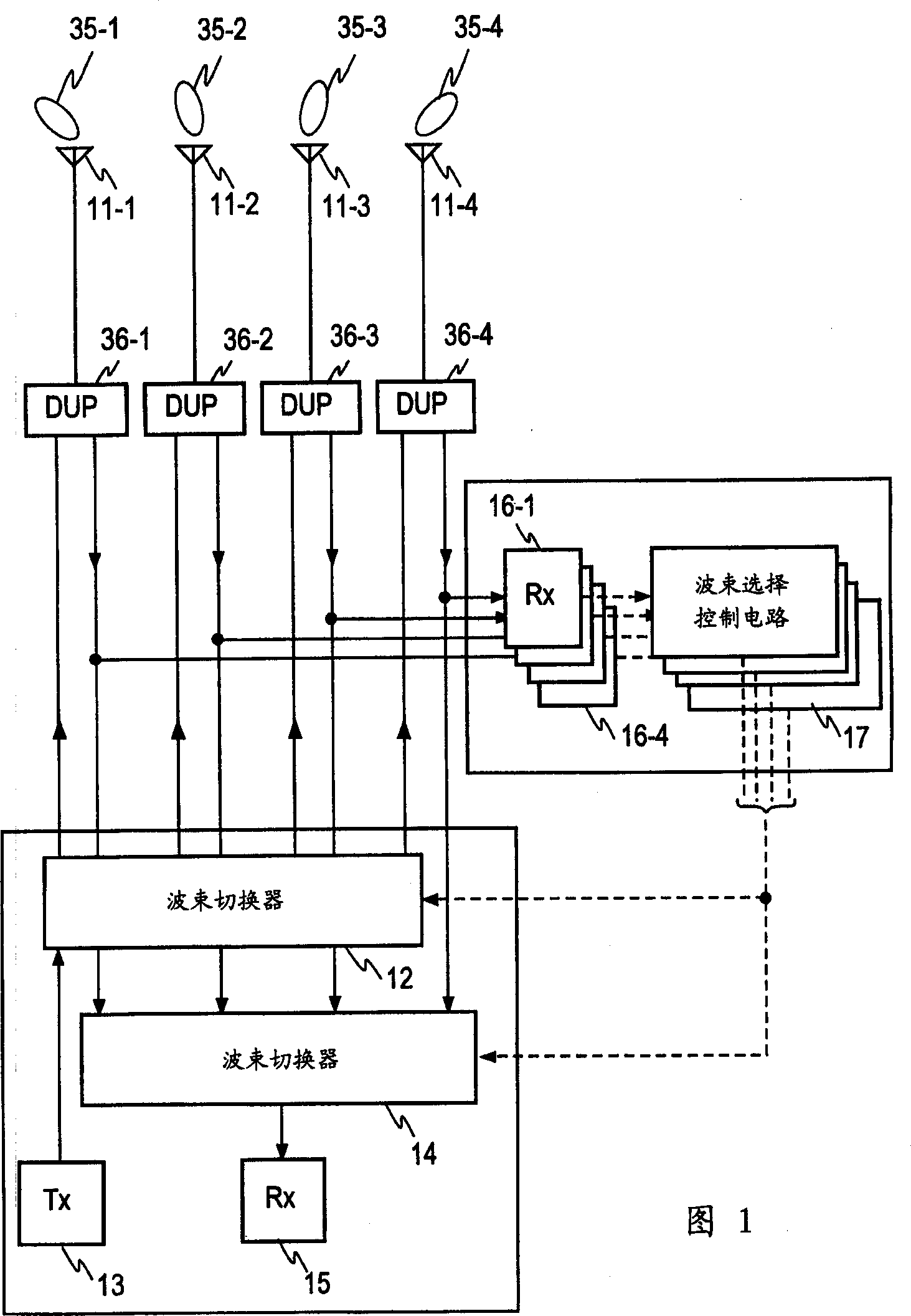
[0009] It can be seen that in traditional base station equipment, since the wide beam angle beam antenna is fixedly assigned to each channel, this means that the equipment will waste radiation power in the direction of its service area (such as a sector), while is not consumed in the desired direction of the mobile station, thereby interfering with other base stations

Method used


Image

  • Mobile communication base station equipment
  • Mobile communication base station equipment
  • Mobile communication base station equipment

Examples


Embodiment Construction

[0050] attached Figure 5A Showing an embodiment according to the first aspect of the present invention, parts corresponding to FIG. 1 are denoted by similar numerals as in FIG. 1 , it will be understood that similar conventional matters are referred to in the following description. In this embodiment, a pair of antennas 21-1 and 21-2 are provided which exhibit wide beam angle directional responses (or wide beam angle beams). Each of the wide beam angle beam antennas 21-1 and 21-2 can substantially cover the service area collectively covered by the narrow beam angle beam antennas 11-1 to 11-4. It will be understood that the antennas 21-1 and 21-2 are located very close to each other so as to be within the order of half of the wavelength (λ) of the radio waves involved and have wide beam angle beams 20 with their central axes parallel to each other. -1 and 20-2.

[0051] The direction finder receiver 22 is connected to one wide beam angle beam antenna 21-1, and the communicat...


PUM


Abstract

A mobile communication base station determines the oncoming direction of a radio wave with a simple arrangement and transmits a narrow angle beam in this direction. Received signals from a pair of wide angle beam antennae 21 - 1 and 21 - 2 having an equal configuration and a common orientation and which are located close to each other are fed to a direction finder receiver 22 and a communication receiver 15 . By utilizing the fact that the both received signals have a coincident amplitude, a phase difference between the received signals is detected. The oncoming direction of the received radio wave (or the direction of a mobile station) is determined on the basis of the phase difference. A beam switcher 12 is controlled so as to connect a transmitter 13 to a narrow angle beam antenna (one of 11 - 1 to 11 - 4 ) which is directed in the oncoming direction thus determined.

Description

technical field [0001] The invention relates to a base station equipment of a mobile communication system, which communicates with a mobile station through a narrow beam angle direction (narrow beam angle beam) antenna to reduce external interference. Background technique [0002] The adaptive array antenna in traditional mobile communication base station equipment is constructed in such a way that multiple receivers are provided for each communication channel, and the antenna weight is adjusted according to the antenna directivity response to control the direction of the main beam to extract the best Receiving the signal, utilizes the antenna counterweight for the best signal while steering the main beam direction according to the transmit antenna directivity response. However, this conventional practice requires providing a plurality of transmitters / receivers for transmission and reception of each channel, and has a disadvantage in that the scale of the equip...

Claims


Application Information

Patent Timeline
Patent Type & Authority Applications(China)
IPC IPC(8): H04B7/155H01Q1/24H01Q3/24H01Q3/26
CPCH01Q3/2605H01Q1/246H01Q3/24H04W16/28H04W52/30H04B7/155
Inventor 山口良寺田矩芳野岛俊雄
Owner NTT DOCOMO INC
Why Eureka
Try Eureka